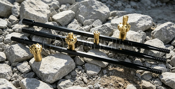

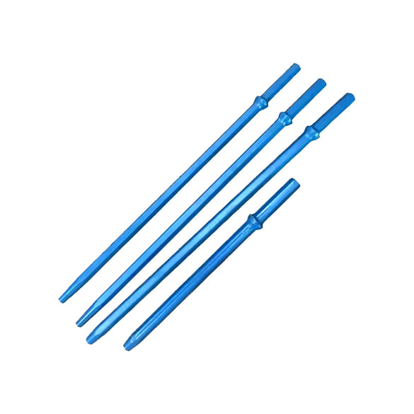
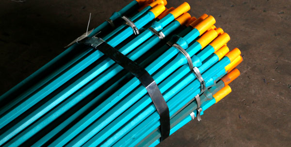
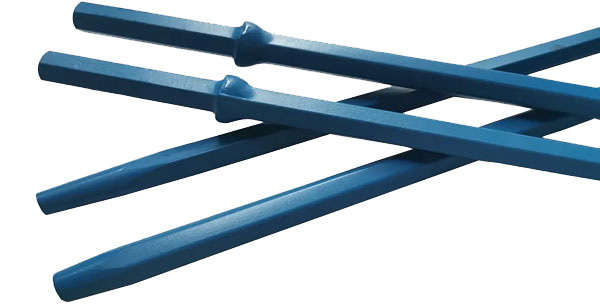
The 7-degree tapered drill rod is a special type of drill bit that has a taper of 7 degrees along its length. This taper design allows the drill bit to gradually increase its diameter as it penetrates into the material being drilled, ensuring smoother and more efficient drilling.
Here is a detailed introduction to the 7-degree tapered drill rod:
Structure and Design:
The 7-degree tapered drill rod is typically made of high-strength steel or tungsten carbide, depending on the intended application and the hardness of the material to be drilled. It consists of a cylindrical shank that connects to the drill machine and a tapered section that gradually widens towards the cutting edge. The taper angle is precisely controlled at 7 degrees to ensure accurate and efficient drilling.
Advantages:
The taper design of the 7-degree drill rod offers several advantages. Firstly, it reduces the resistance encountered by the drill bit as it penetrates into the material, allowing for smoother and faster drilling. Secondly, the tapered shape helps to distribute the drilling force more evenly, reducing the risk of the bit breaking or jamming. Additionally, the gradual increase in diameter can improve hole quality by reducing the chance of cracking or chipping the material around the hole.
Applications:
The 7-degree tapered drill rod is commonly used in various industries and applications where drilling into hard materials is required. It is particularly suitable for drilling into metals, alloys, and other tough materials. It can be used in machining operations, construction projects, and even in the oil and gas industry for drilling into rock formations.
Selection and Use:
When selecting a 7-degree tapered drill rod, it is important to consider the material being drilled, the desired hole diameter and depth, and the specific requirements of the drilling operation. It is also essential to use the drill rod with the appropriate drill machine and to maintain it properly to ensure its long-term performance.
In summary, the 7-degree tapered drill rod is a highly effective tool for drilling into hard materials. Its taper design allows for smoother and faster drilling, while its high-strength material ensures durability and performance. It is a valuable addition to any toolbox for those who require precision and efficiency in their drilling operations.
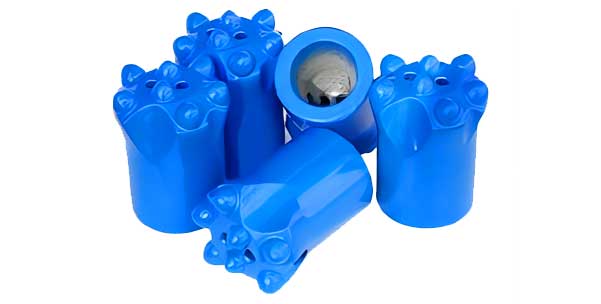
The service life of a button bit R32 depends on various factors, including the quality of the bit, the type of material it is drilling into, the drilling conditions, and the maintenance and usage practices. It’s important to note that there is no fixed or standard lifespan for any drill bit, as it is highly dependent on the specific circumstances.
Here are some factors that can affect the service life of a button bit R32:
Material Quality: The material used to make the bit plays a crucial role in its durability. High-quality materials can withstand more wear and tear, leading to a longer lifespan.
Drilling Material: Different materials have different hardness and abrasiveness, which can affect the wear rate of the bit. Drilling into harder or abrasive materials will generally shorten the bit’s lifespan.
Drilling Conditions: Factors such as drilling pressure, speed, and lubrication can significantly impact the bit’s performance and lifespan. Operating within the recommended parameters for the bit can help extend its service life.
Maintenance: Regular cleaning and inspection of the bit can help identify wear and tear early on, allowing for timely replacement or repair. This can prevent premature failure and extend the bit’s useful life.
Usage Practices: Proper usage practices, such as avoiding excessive force or improper handling, can minimize damage to the bit and prolong its lifespan.
To maximize the service life of your button bit R32, it’s recommended to:
Follow the manufacturer’s instructions and recommendations for usage and maintenance.
Use the bit for the appropriate material and within the recommended drilling conditions.
Regularly inspect the bit for wear and tear, and replace it when necessary.
Store the bit properly to prevent damage from corrosion or impact.
Remember, the service life of a button bit R32 is variable and depends on multiple factors. By following best practices and maintaining the bit properly, you can help ensure it lasts as long as possible.
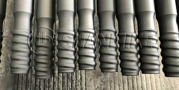
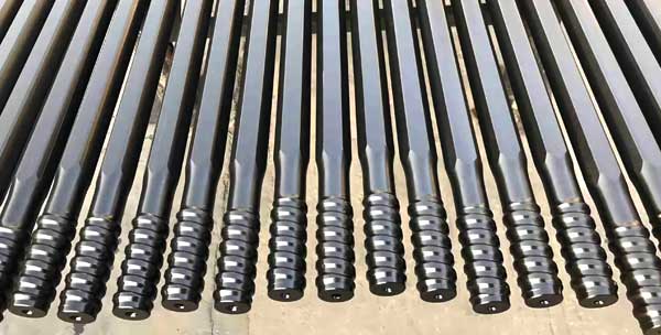
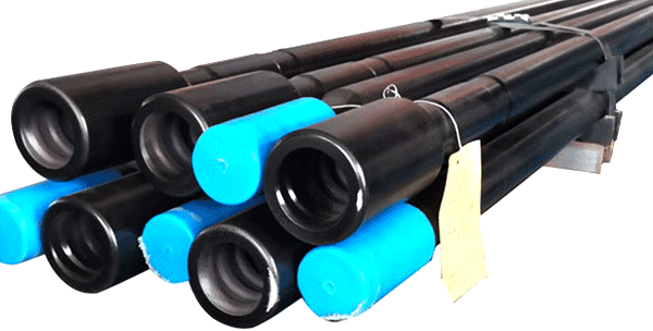
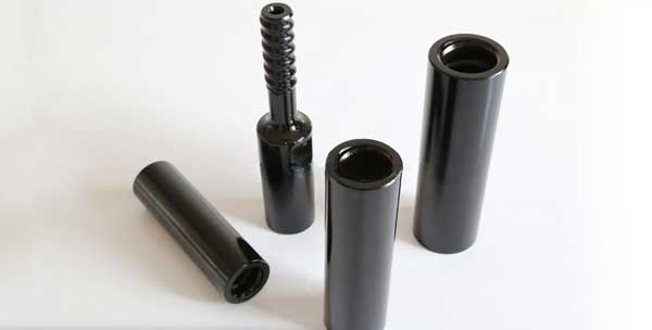
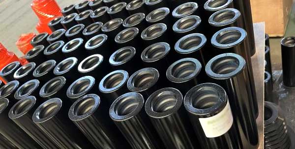
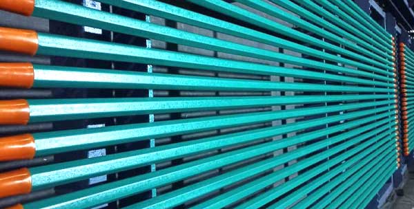
Shandike specializes in the production of rock drill tools (rock drill accessories, rock drill spare parts), such as drill rods, shank adapter, drill bits, etc. Shandike drill rod has the characteristics of tight connection, good energy transfer effect, strong wear resistance and convenient disassembly. Shandike drill rod adopts advanced processing technology, which can effectively reduce the risk of drill rod breaking at the threaded end. The wear of the male thread part and the female thread part at both ends of each drill rod is balanced, which can effectively improve the use efficiency and use time of the drill rod.
T38 MF Drill Rod is a very commonly used rock drilling rod, which can be widely used in bench drilling, production drilling and long-hole drilling.
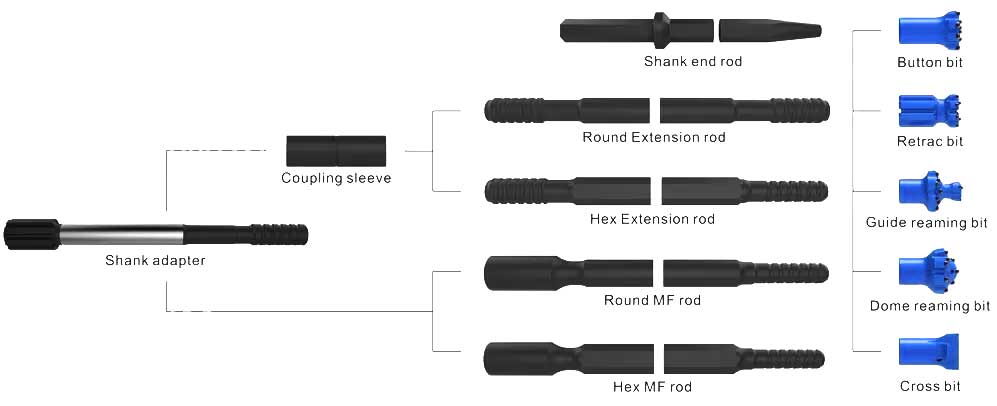
A drill rod, also known as a drill pipe, is a tubular steel member with threaded connections at both ends. It is a crucial component in drilling operations, especially in the oil and gas industry. The primary purposes of a drill rod are as follows:
In summary, the drill rod is a vital component in drilling operations, responsible for connecting the surface equipment to the drill bit, transmitting force and mud, and withstanding various loads and pressures. It plays a crucial role in ensuring the efficient and safe execution of drilling activities.
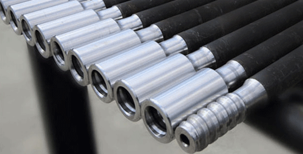
Hexagonal drill rods are produced by CNC machining and advanced heat treatment on the base of the same steels as Sandvik.
• Thread size: R22, R25, R28, SSR28, R32, SSR32, R35, SSR35, R38, T38, other.
• Rod size: Hex.22, Hex.25, Hex.28, Hex.32, Hex.35.
• Length: 2100mm to 6095mm.
• Carburizing process is applied to promote surface hardness, thus grant better wearing quality and lifespan for the drill rods;
• 23CrNi3Mo, which is in same league as Sandvik Sandbar 64, is applied as drill rod material.
• Cost-effective, good performance with reasonable price.
• Complete types of drill rod for various drilling scenarios.
Drilling duties in tunneling, construction, mining, quarrying, etc.
| Drifting and Tunneling Rod / MF(Speed) Rod |
| Description | Length | Diameter | Weight | ||
| mm | feet | mm | inch | kg | |
| Drifter RodR32 – Hex.25 – R25 | 2100 | 6′ 10 5/8” | 25 | 1” | 8.60 |
| 2200 | 7′ 2 5/8” | 25 | 1” | 9.00 | |
| 2400 | 7′ 10 1/2” | 25 | 1” | 9.30 | |
| 2600 | 8′ 6 3/8” | 25 | 1” | 10.0 | |
| 2800 | 9′ 2 1/4” | 25 | 1” | 10.8 | |
| 3090 | 10′ 1 5/8” | 25 | 1” | 12.0 | |
| Drifter RodR32 – Hex.28 – R28 | 2400 | 7′ 10 1/2” | 28 | 1 1/8” | 11.9 |
| 2600 | 8′ 6 3/8” | 28 | 1 1/8” | 13.6 | |
| 3050 | 10′ | 28 | 1 1/8” | 17.0 | |
| 3700 | 12′ | 28 | 1 1/8” | 18.5 | |
| 4000 | 13′ 1/2” | 28 | 1 1/8” | 21.0 | |
| 4305 | 14′ | 28 | 1 1/8” | 23.5 | |
| Drifter RodR38 – Hex.32 – R32 | 3050 | 10′ | 32 | 1 1/4” | 19.5 |
| 3700 | 12′ | 32 | 1 1/4” | 24.0 | |
| 4305 | 14′ | 32 | 1 1/4” | 27.9 | |
| 4915 | 16′ | 32 | 1 1/4” | 31.8 | |
| Drifter RodR38 – Hex.35 – R32 | 3050 | 10′ | 35 | 1 3/8” | 21.4 |
| 3700 | 12′ | 35 | 1 3/8” | 29.0 | |
| 4305 | 14′ | 35 | 1 3/8” | 33.8 | |
| 4915 | 16′ | 35 | 1 3/8” | 38.6 | |
| 5525 | 18′ | 35′ | 1 3/8′ | 43.4 | |
| Drifter RodT38 – Hex.35 – R32 | 3700 | 12′ | 35 | 1 3/8” | 29.0 |
| 4305 | 14′ | 35 | 1 3/8” | 33.8 | |
| 4915 | 16′ | 35 | 1 3/8” | 38.6 | |
| 5525 | 18′ | 35 | 1 3/8” | 43.4 | |
| MF(Speed) Drifter RodT38 – Hex.35 – R32 | 3700 | 12′ | 35 | 1 3/8” | 29.2 |
| 4305 | 14′ | 35 | 1 3/8” | 34.0 | |
| 4915 | 16′ | 35 | 1 3/8” | 38.8 | |
| 5525 | 18′ | 35 | 1 3/8” | 43.6 | |
Made from the same steels as Sandvik, produced by CNC machining and advanced heat treatment.
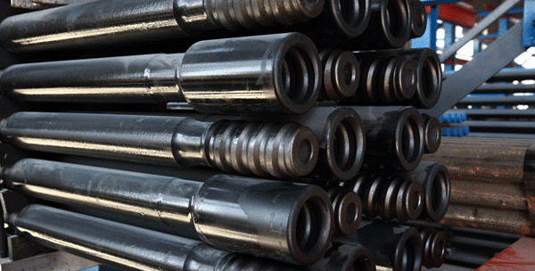
The threaded drill rods, working with hydraulic drill rigs and hydraulic jumbos, have main threads of R22,R25,R28,R32,TR35,T38,T45,T51,ST58,ST68 and T60.
• Carburizing process is applied to promote surface hardness, thus grant better wearing quality and lifespan for the drill rods;
• 23CrNi3Mo, which is in same league as Sandvik Sandbar 64, is applied as drill rod material.
• Cost-effective, good performance with reasonable price.
• Complete types of drill rod for various drilling scenarios.
The threaded drill rods are divided into MF rods and extension rods, which are widely used in open-pit mining, underground mining, tunneling, anchoring, furnace tapping, tunnel construction, hydropower engineering, quarrying and construction.
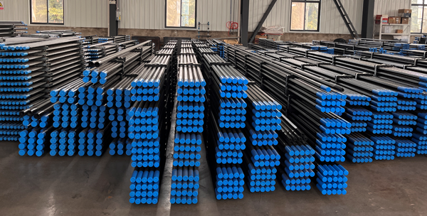
SHANDIKE is the first Chinese factory to manufacture drill rods and ranks the forefront in the industry in China regarding quality, sales volume, export volume, specification varieties and matching capacity.
| Bench and Production Rods, Extension Rods, MF(Speed) Rods |
| Description | Length | Diameter | Weight | ||
| mm | feet | mm | inch | kg | |
| Extension RodR32 – Round32 – R32 | 2435 | 8′ | 32 | 1 1/4” | 14.20 |
| 3050 | 10′ | 32 | 1 1/4” | 17.80 | |
| 3660 | 12′ | 32 | 1 1/4” | 21.30 | |
| MF (Speed) RodR32 – Round32 – R32 | 3050 | 10′ | 32 | 1 1/4” | 17.90 |
| 3660 | 12′ | 32 | 1 1/4” | 21.45 | |
| 4270 | 14′ | 32 | 1 1/4” | 25.10 | |
| Extension RodR38 – Round39 – R38 | 3050 | 10′ | 39 | 1 17/32” | 25.50 |
| 3660 | 12′ | 39 | 1 17/32” | 30.60 | |
| 4270 | 14′ | 39 | 1 17/32” | 35.40 | |
| MF (Speed) RodR38 – Round39 – R38 | 3050 | 10′ | 39 | 1 17/32” | 26.50 |
| 3660 | 12′ | 39 | 1 17/32” | 31.60 | |
| 4270 | 14′ | 39 | 1 17/32” | 36.40 | |
| Extansion RodT38 – Round39 – T38 | 3050 | 10′ | 39 | 1 17/32” | 25.50 |
| 3660 | 12′ | 39 | 1 17/32” | 30.60 | |
| 4270 | 14′ | 39 | 1 17/32” | 35.40 | |
| MF (Speed) RodT38 – Round39 – T38 | 3050 | 10′ | 39 | 1 17/32” | 26.50 |
| 3660 | 12′ | 39 | 1 17/32” | 31.60 | |
| 4270 | 14′ | 39 | 1 17/32” | 36.40 | |
| Extension RodT45 – Round46 – T45 | 3050 | 10′ | 46 | 1 3/4” | 35.80 |
| 3660 | 12′ | 46 | 1 3/4” | 43.00 | |
| 4270 | 14′ | 46 | 1 3/4” | 50.10 | |
| MF (Speed) RodT45 – Round46 – T45 | 3050 | 10′ | 46 | 1 3/4” | 36.40 |
| 3660 | 12′ | 46 | 1 3/4” | 43.70 | |
| 4270 | 14′ | 46 | 1 3/4” | 50.70 | |
| Extension RodT51 – Round52 – T51 | 3660 | 12′ | 52 | 2” | 54.20 |
| 4270 | 14′ | 52 | 2” | 63.50 | |
| MF (Speed) RodT51 – Round52 – T51 | 3660 | 12′ | 52 | 2” | 55.70 |
| 4270 | 14′ | 52 | 2” | 64.80 | |
| Extension RodR32 – Round32 – R32 | 915 | 3′ | 32 | 1 1/4” | 5.50 |
| 1220 | 4′ | 32 | 1 1/4” | 7.32 | |
| 1525 | 5′ | 32 | 1 1/4” | 9.18 | |
| 1830 | 6′ | 32 | 1 1/4” | 10.95 | |
| MF (Speed) RodR32 – Round32 – R32 | 915 | 3′ | 32 | 1 1/4” | 5.45 |
| 1220 | 4′ | 32 | 1 1/4” | 7.28 | |
| 1525 | 5′ | 32 | 1 1/4” | 9.10 | |
| 1830 | 6′ | 32 | 1 1/4” | 10.72 | |
| Extension RodT38 – Round39 – T38 | 1220 | 4′ | 39 | 1 17/32” | 9.20 |
| 1525 | 5′ | 39 | 1 17/32” | 10.25 | |
| 1830 | 6′ | 39 | 1 17/32” | 15.30 | |
| MF (Speed) RodT38 – Round39 – T38 | 1220 | 4′ | 39 | 1 17/32” | 9.50 |
| 1525 | 5′ | 39 | 1 17/32” | 11.25 | |
| 1830 | 6′ | 39 | 1 17/32” | 16.30 | |
| MF (Speed) RodT45 – Round46 – T45 | 1525 | 5′ | 46 | 1 3/4” | 18.50 |
| 1830 | 6′ | 46 | 1 3/4” | 22.20 | |
| MF (Speed) RodT51 – Round52 – T52 | 1525 | 5′ | 52 | 2” | 17.85 |
| 1830 | 6′ | 52 | 2” | 28.10 | |
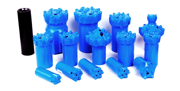
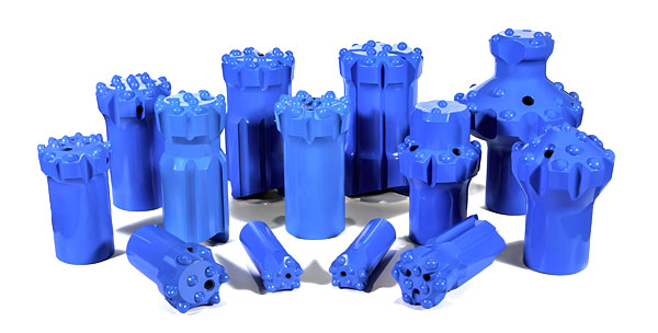
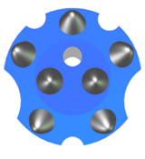
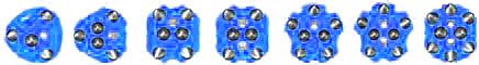
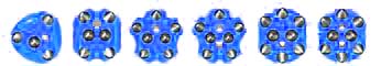
Threaded drill bits are also knowm as button bits which conmect with threaded dri11 rods by threads to transfer impactpower and rotation torque for breaking rocks, The threaded dri11 bits, working with hydraulic dri11 rigs and hydraulic jumboshave main threads of R22, R25,R28, R32, TR35, T38, T45, T51, ST58, ST68, EL60, EL68 and T60.
Material: premium alloy steels
Insert Tech: hot-pressed carbide inserts
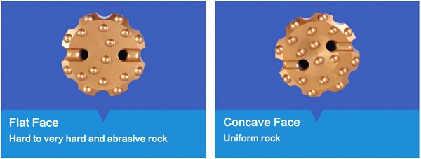
Face Type: Flat front( for drilling in medium to hard and abrasive rock formations
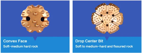
Drop center front( Reduced hole deviation for drilling in medium-hard rock formations)
Button Type: Hemispherical/Parabolic/Ballistic / Conical
Color: Green, Orange, Gold, Black or based on customer requirements.
Processing: CNC milling and proprietary heat treatment process
Alloy buttons are hot mounted into the drill bit, ensuring the bit good accuracy and durability;
Reliability ensured by premium drill bit materials and premium alloy button;
Different types designed for different drilling scenarios and rock conditions;
High speed and drilling efficiency;
Cost-effective, good performance with reasonable price.
Threaded drill bits are widely used in openpit mining, underground muning,tumeling, anchoring, furmace tapping, tunnel construction, hydropower engineering, quarrying and construction.
| Threaded Button Bits | |
| Thread Type | R22 R23 R25 R28 R32 R35 R38 TR28 TR32 TR35 |
| T38 T45 T51ST58 GT60 | |
| ST58 GT60 ST68 EL68 EL60 | |
| Diameter of Bit | 28-165mm (R Threads) |
| 64-178mm (T Threads) | |
| 89-152mm (Other Threads) | |
| Skirt Type | Retrac, Reinforced, Standard |
| Face Design | Flat Face , Drop Center Convex |
| Button Shape | Concinal Semi Ballsitic Parabolic Full-Spherical , Hemispherical |
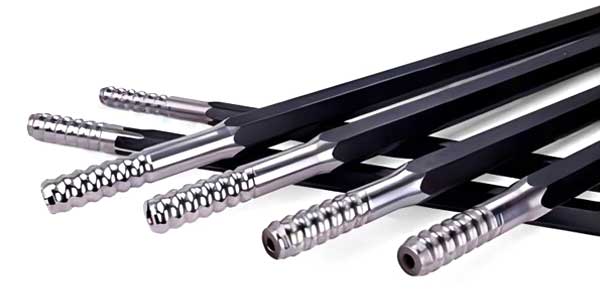
Top hammer shank adaptors, the role of which in rock drilling is to directly bear the impact energy and torque of the rock drill, and is used to transfer the energy from drill rig to drill rod. One end of the shank adaptor is connected to drill rig, and another end is connected to drill rod, so that the energy of drill rig can be transmitted to drill bit, and finally achieve the purpose of drilling.
The specification and hardness of top hammer shank adaptor have a great influence on the rock drilling speed and the life of the rock drill. The hardness of the top hammer shank adaptors for drill should be appropriate, the service life is short if the rock drill shank is too soft, the piston is vulnerable to damage if the drill shank adapter is too hard. Shandike shank adaptor factory has accurate specifications, smooth surface, suitable hardness, the cross-section is perpendicular to the axis, and closely coincides with rock drill sleeve.
Shandike offers male and female threaded shank adapter, also called striking bar or shank rod, such as T38 shank adapter, T45 shank adapter, T51 shank adaptor, etc. Our China shank adapters are suitable for various brands of rock drills, such as Atlas Copco, Sandvik, Furukawa, Montabert, Ingersoll-Rand, Tamrock, etc., and the rock drill shank adapter (drill shank adaptor) also can be designed according to customer needs.
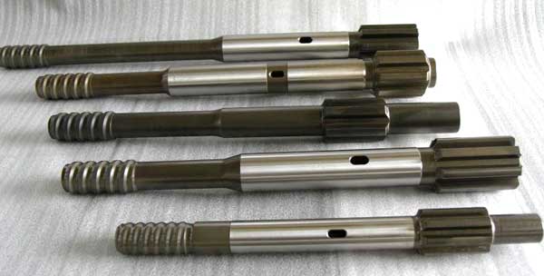
• Thread type: R25, R28, R32, R35, R38, T38, T45, T51, etc.
• Diameter: 32mm-70mm
• Length: 273mm-885mm
• Applicable rock drill brand: Atlas Copco, Tamrock, Ingersoll Rand, Boart Longyear, Furukawa, Montabert, Soonsan, Everdigm, etc.
Drilling works for blasting duties in tunneling, construction, mining, quarrying, etc.
Rock Drill | Shank Adapters | Thread | Length (mm) |
Atlas Copco COP1036/1238/1038HB | 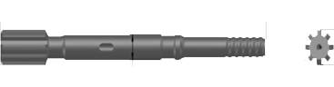 | R32 T38 T45 | 500 500 500 |
Atlas Copco COP1432/COP1532/ COP1440/COP1838HD/ME | 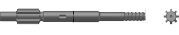 | R32 R38 T38 R32 TC35 T38 R32 R35 R38 T45 T51 | 435 435 435 525 525 525 525 525 525 525 525 |
Atlas Copco COP1440/COP1550/COP1838 | 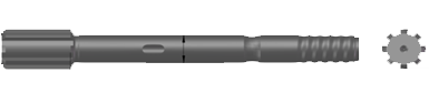 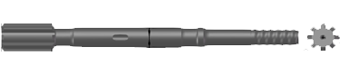 | R32 R38 T38 R38 T38 R32 TC35 R38 T38 | 435 435 435 455 455 525 525 525 525 |
Atlas Copco COP1840EX/COP1850EX | 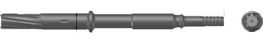 | T38 T45 T51 | 770 770 770 |
Atlas Copco COP1840/COP1850 | 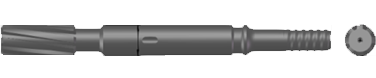 | T45 T51 | 565 565 |
Tamrock HL300 | 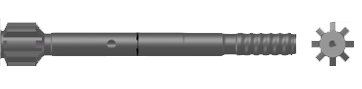 | R32 | 400 |
Tamrock HL500-45/510-45 | 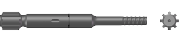 | R32 T38 T45 | 550 550 550 |
Tamrock HLX5/HLX5T | 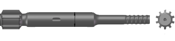 | R32 R38 T38 R32 T38 T45 | 500 500 500 575 575 575 |
Tamrock HL650-45/700-45/700T-45/ 710-45/800T-45 | 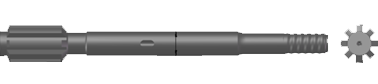 | T38 T45 | 600 600 |
Tamrock HL1000/HL1010/HL1000S/ HL1010S-52 | 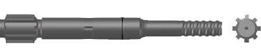 | T45 T51 T45 T51 | 670 670 590 590 |
Furukawa HD609 | 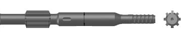 | T38 T38 T45 | 620 690 620 |
Furukawa HD612 | 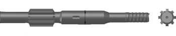 | T38 T45 T45 | 710 710 720 |
Furukawa HD709 | 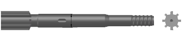 | T38 | 620 |
Furukawa HD712 | 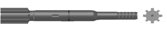 | T45 T51 T45 T51 | 590 590 790 790 |
Montabert HC40 |  | R32 R38 | 447 447 |
Montabert HC80, HC120 |  | T45 | 490 |
Ingersoll-Rand URD475/URD550/VL120/ EVL130/VL140 |  | R32 R32 T38 T45 | 330 380 380 380 |
Ingersoll-Rand YH65/YH80 |  | T38 T45 | 500 500 |
Ingersoll-Rand YH65RP/YH70RP/ YH75RP/YH80RP |  | T38 T45 | 700 700 |
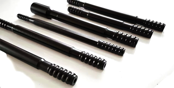
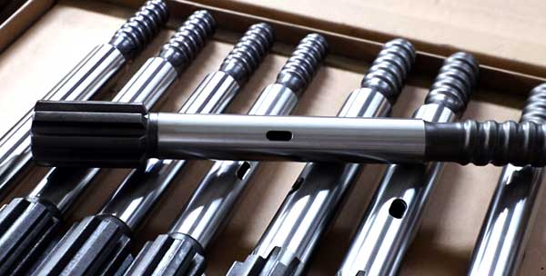
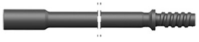
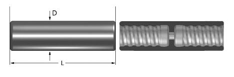
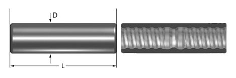
Rock Drill MF Rod (commonly referred to as Speed Drill Rod) features a male-female threaded configuration, with a male thread at one end and a female thread at the opposite end. This design enables direct coupling with the shank adapter without requiring an additional sleeve connector, thereby resolving the inherent issue of vibration-induced instability in traditional equal-diameter threaded joints. The optimized rapid transition mechanism between male and female threads enhances tool-change efficiency during drilling operations, significantly improving overall operational productivity.

As an ISO 9001:2015-certified manufacturer, we operate two fully automated production facilities in China, equipped with:
Our rods are fabricated from modified AISI 4140 Cr-Mo-V alloy steel (ASTM standard), subjected to a triple heat treatment process:
Resulting in critical performance metrics:
We supply a full range of quick-change drill rods compliant with ISO 1718 and DIN 2050 standards, covering mainstream specifications:
Field tests conducted by the China Geological Equipment Certification Center (CGEC) demonstrate:
Average drilling efficiency in granite formations: 1.8 m/min (27% improvement over conventional systems).
-40°C low-temperature torque retention: 90% of rated capacity.
| Length | Diameter | Weight | Model No. | |||
| [mm] | [ft-in] | [mm] | [in] | [kg] | ||
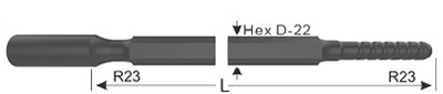 | 2095 | 6′ 10 1/2“ | 22 | 7/8″ | 6.4 | MF-R23-H22-2095 |
| MF rod, Hex 22, R23 – R23 | 3050 | 10′ | 22 | 7/8″ | 10 | MF-R23-H22-3050 |
| Length | Diameter | Weight | Model No. | |||
| [mm] | [ft-in] | [mm] | [in] | [kg] | ||
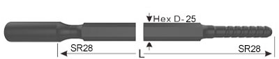 | 3050 | 10′ | 25 | 1″ | 12.1 | MF-SR28-H25-3050 |
| MF rod, Hex 25, SR28 – SR28 | ||||||
 | 1200 | 3′ 11 1/4″ | 28 | 1 1/8″ | 6.2 | MF-SR28-H28-1200 |
| MF rod, Hex 28, SR28 – SR28 | 2000 | 6′ 6 3/4″ | 28 | 1 1/8″ | 10.5 | MF-SR28-H28-2000 |
| Length | Diameter | Weight | Model No. | |||
| [mm] | [ft-in] | [mm] | [in] | [kg] | ||
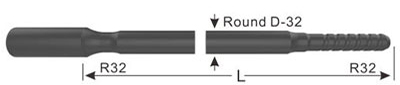 | 915 | 3′ | 32 | 1 1/4″ | 5.5 | MF-R32-D32-915 |
| MF rod, Round 32, R32 – R32 | 1220 | 4′ | 32 | 1 1/4″ | 7.5 | MF-R32-D32-1220 |
| 1525 | 5′ | 32 | 1 1/4″ | 9.1 | MF-R32-D32-1525 | |
| 1830 | 6′ | 32 | 1 1/4″ | 11 | MF-R32-D32-1830 | |
| 3050 | 10′ | 32 | 1 1/4″ | 18 | MF-R32-D32-3050 | |
| 3660 | 12′ | 32 | 1 1/4″ | 21 | MF-R32-D32-3660 | |
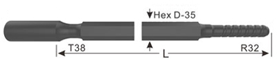 | 3700 | 12′ 1 5/8″ | 35 | 1 3/8″ | 29 | MF-T38/R32-H35-3700 |
| MF Drifter rod, Hex 35, T38 – R32 | 4305 | 14′ 1 1/2″ | 35 | 1 3/8″ | 34 | MF-T38/R32-H35-4305 |
| Length | Diameter | Weight | Model No. | |||
| [mm] | [ft-in] | [mm] | [in] | [kg] | ||
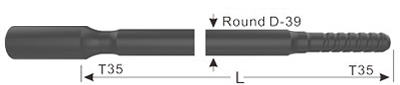 | 1830 | 6′ | 39 | 1 1/2″ | 16 | MF-T35-D39-1830 |
| MF rod, Round 39, T35 – T35 | 3050 | 10′ | 39 | 1 1/2″ | 25 | MF-T35-D39-3050 |
| 3660 | 12′ | 39 | 1 1/2″ | 32 | MF-T35-D39-3660 | |
| 4265 | 14′ | 39 | 1 1/2″ | 35 | MF-T35-D39-4265 | |
| 4875 | 16′ | 39 | 1 1/2″ | 40 | MF-T35-D39-4875 | |
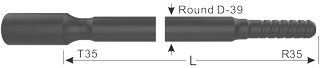 | 4305 | 14′ 1 1/2″ | 39 | 1 1/2″ | 35 | MF-T35/R35-D39-4305 |
| MF Drifter rod, Round 39, T35 – R35 | 4915 | 16′ 1 1/2″ | 39 | 1 1/2″ | 40 | MF-T35/R35-D39-4915 |
| 5525 | 18′ 1 1/2″ | 39 | 1 1/2″ | 45 | MF-T35/R35-D39-5525 | |
| 6135 | 20′ 1 1/2″ | 39 | 1 1/2″ | 50 | MF-T35/R35-D39-6135 | |
| Length | Diameter | Weight | Model No. | |||
| [mm] | [ft-in] | [mm] | [in] | [kg] | ||
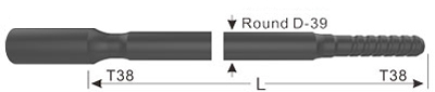 | 915 | 3′ | 39 | 1 1/2″ | 8.1 | MF-T38-D39-915 |
| MF rod, Round 39, T38 – T38 | 1220 | 4′ | 39 | 1 1/2″ | 11 | MF-T38-D39-1220 |
| 1525 | 5′ | 39 | 1 1/2″ | 12 | MF-T38-D39-1525 | |
| 1830 | 6′ | 39 | 1 1/2″ | 15 | MF-T38-D39-1830 | |
| 3050 | 10′ | 39 | 1 1/2″ | 25 | MF-T38-D39-3050 | |
| 3660 | 12′ | 39 | 1 1/2″ | 30 | MF-T38-D39-3660 | |
| 4265 | 14′ | 39 | 1 1/2″ | 36 | MF-T38-D39-4265 | |
| 4875 | 16′ | 39 | 1 1/2″ | 41 | MF-T38-D39-4875 | |
| Length | Diameter | Weight | Model No. | |||
| [mm] | [ft-in] | [mm] | [in] | [kg] | ||
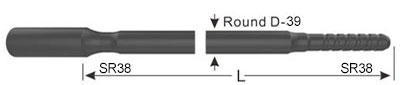 | 1830 | 6′ | 39 | 1 1/2″ | 15.3 | MF-SR38-D39-1830 |
| MF rod, Round 39, SR38 – SR38 | 3050 | 10′ | 39 | 1 1/2″ | 25 | MF-SR38-D39-3050 |
| 4920 | 16′ 1 3/4″ | 39 | 1 1/2″ | 40 | MF-SR38-D39-4920 | |
| Length | Diameter | Weight | Model No. | |||
| [mm] | [ft-in] | [mm] | [in] | [kg] | ||
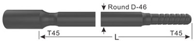 | 1220 | 4′ | 46 | 1 3/4″ | 14 | MF-T45-D46-1220 |
| MF rod, Round 46, T45 – T45 | 1525 | 5′ | 46 | 1 3/4″ | 18 | MF-T45-D46-1525 |
| 1830 | 6′ | 46 | 1 3/4″ | 21 | MF-T45-D46-1830 | |
| 3050 | 10′ | 46 | 1 3/4″ | 35 | MF-T45-D46-3050 | |
| 3660 | 12′ | 46 | 1 3/4″ | 41 | MF-T45-D46-3660 | |
| 4265 | 14′ | 46 | 1 3/4″ | 48 | MF-T45-D46-4265 | |
| 6095 | 20′ | 46 | 1 3/4″ | 69 | MF-T45-D46-6095 | |
| Length | Diameter | Weight | Model No. | |||
| [mm] | [ft-in] | [mm] | [in] | [kg] | ||
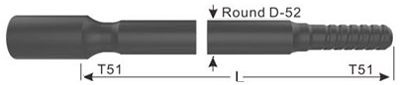 | 1525 | 5′ | 52 | 2″ | 23 | MF-T51-D52-1525 |
| MF rod, Round 52, T51 – T51 | 1830 | 6′ | 52 | 2″ | 27 | MF-T51-D52-1830 |
| 3660 | 12′ | 52 | 2″ | 50 | MF-T51-D52-3660 | |
| 4265 | 14′ | 52 | 2″ | 57 | MF-T51-D52-4265 | |
| 5485 | 17’11″ | 52 | 2″ | 72 | MF-T51-D52-5485 | |
| 6095 | 20′ | 52 | 2″ | 87 | MF-T51-D52-6095 | |
| Length | Diameter | Weight | Model No. | |||
| [mm] | [ft-in] | [mm] | [in] | [kg] | ||
 | 3660 | 12′ | 60 | 2 3/8″ | 73 | MF-GT60-D60-3660 |
| MF rod, Round 60, GT60 – GT60 | 4265 | 14′ | 60 | 2 3/8″ | 86 | MF-GT60-D60-4265 |
| 5485 | 18′ | 60 | 2 3/8″ | 107 | MF-GT60-D60-5485 | |
| 6095 | 20′ | 60 | 2 3/8″ | 120 | MF-GT60-D60-6095 | |
 | 4265 | 14′ | 64 | 2 1/2″ | 92 | MF-GT60-D64-4265 |
| MF rod, Round 64, GT60 – GT60 | ||||||
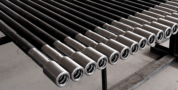
Drill Rod Coupling Sleeve is a sleeve-shaped rock drilling component with internal threads for connecting shank adapter and drill rod, or drill rod and drill rod. We produce and provide three types of drill rod couplings – semi bridge couplings, full bridge couplings, and crossover couplings, which can meet the requirements of all applications.
Standard coupling sleeve, also known as semi bridge coupling sleeve, has a section of the bridge without a thread in the middle. The threaded part of the drill pipe cannot be screwed through the bridge part of the coupling, and the end of the thread can closely adhere to the casing bridge zone. Standard coupling sleeve is particularly suitable for high-torque drilling rigs. Most rope thread (R thread) and trapezoidal thread (T thread) coupling sleeves are with half-bridge type. The half-bridge type is by far the most widely used couplings.
Full bridge coupling sleeve can completely eliminate the looseness of the coupling sleeves along with the threaded connection. It is mainly used in surface mining, with better disassembly characteristics, firmer connections, and almost no clamping situation.

Crossover couplings are used to convert different thread types or thread diameter sizes.
| Coupling Sleeve | ||||
| Thread | Diameter | Length | ||
| mm | inch | mm | inch | |
| R25 | 35 | 1 19/50 | 150 | 5 9/10 |
| R28 | 40 | 1 29/50 | 155 | 6 1/10 |
| R32 | 45 | 1 3/4 | 170 | 6 57/64 |
| R38 | 55 | 2 5/32 | 170 | 6 57/64 |
| T38 | 55 | 2 5/32 | 190 | 7 33/64 |
| T45 | 63 | 2 15/32 | 210 | 8 17/64 |
| T45 | 66 | 2 19/32 | 210 | 8 17/64 |
| T51 | 72 | 2 7/8 | 235 | 9 1/4 |
| T51 | 76 | 3 | 235 | 9 1/4 |
| Adapter Coupling / Crossover Coupling | |||||
| Thread | Diameter | Length | |||
| A | B | mm | inch | mm | inch |
| R25 | R32 | 45 | 1 3/4 | 170 | 6 57/64 |
| R28 | R32 | 45 | 1 3/4 | 170 | 6 57/64 |
| R32 | R38 | 55 | 2 5/32 | 180 | 7 1/8 |
| R32 | T38 | 55 | 2 5/32 | 180 | 7 1/8 |
| R38 | T38 | 55 | 2 5/32 | 190 | 7 33/64 |
Tapered drill rod effective lengths are measured from the collar to the bit end, which are usually from 0.6meter to 3.6 meters.
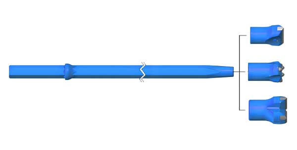
Parameters
Shank sizes: Hex.19mm, Hex. 22mm, Hex.25mm
Taper degrees: 7°, 11°, 12°.
Length: 400 – 8000mm.
Specifications:
Drilling duties in tunneling, construction, mining, quarrying, etc.
| 22mm(7/8″)Tapered drill rods | L | Taper Degree | Weight (kg) | |
| mm | foot/inch | |||
H22×108 Shank  | 500 | 1′ 5/8″ | 7o | 1.5 |
| 800 | 2′7 1/2″ | 2.4 | ||
| 1000 | 3′3 3/8″ | 3 | ||
| 1200 | 3′11 1/4″ | 3.6 | ||
| 1500 | 4′ 11″ | 4.5 | ||
| 1800 | 5′10 7/8″ | 5.5 | ||
| 2000 | 6′6 3/4″ | 6.1 | ||
| 2200 | 7′2 5/8″ | 6.7 | ||
| 2500 | 8′2 3/8″ | 7.6 | ||
| 3000 | 9′10 1/8″ | 9.1 | ||
| 3500 | 11′5 3/4″ | 10.6 | ||
| 4000 | 13′1 1/2″ | 12.1 | ||
| 4500 | 14′9 1/8″ | 13.6 | ||
| 5000 | 16′4 5/8″ | 15.1 | ||
| 6000 | 19′8 1/4″ | 18.2 | ||
| 7000 | 22′11 5/8″ | 21.2 | ||
| 8000 | 26′ 3″ | 24.2 | ||
H22×108 Shank | 800 | 2′7 1/2″ | 12o | 2.4 |
| 1200 | 3′11 1/4″ | 3.6 | ||
| 1600 | 5′ 3″ | 4.9 | ||
| 2200 | 7′2 5/8″ | 6.7 | ||
| 2400 | 7′10 1/2″ | 7.3 | ||
| 3200 | 10′ 6″ | 9.7 | ||
H22×108 Shank | 1800 | 5′10 7/8″ | 7o | 5.5 |
| 2000 | 6′6 3/4″ | 6.1 | ||
| 2500 | 8′2 3/8″ | 7.6 | ||
| 3000 | 9′10 1/8″ | 9.1 | ||
| 3500 | 11′5 3/4″ | 10.6 | ||
| 4000 | 13′1 1/2″ | 12.1 | ||
| 5000 | 16′4 5/8″ | 15.1 | ||
Taper bits(pneumatic drill bit,air drill bits), especially Tapered button bits are the most popular tapered drill bits with a wide selection of head diameters from 26mm to 48mm. With carbide buttons hot pressed on the bit skirts, Pneumatic rock drill bits(tapered button bits) have a good drilling performance and are excellent in longevity.

Taper drill bits are connected to taper drill rods for drilling duties, suitable for tunneling, construction, mining, quarrying, etc.
 |  |  |
| Chisel Taper Bit | Cross Taper Bit | Button Taper Bit |
 | Taper Chisel Bits Taper Degree: 4°46′, 6°, 7° Diameter: 26-43mm |
 | Taper Cross Bits Taper Degree: 4°46′, 6°, 7°, 11°, 12° Diameter: 32-46mm |
 | 4° 46′ Taper Button Bits Taper Degree: 4°46′ Diameter: 36-43mm |
 | 7° Taper Button Bits Taper Degree: 7° Diameter: 32-41mm |
 | 11° Taper Button Bits Taper Degree: 11° Diameter: 32-41mm |
 | 12° Taper Button Bits Taper Degree: 12° Diameter: 30-42mm |
Fully-carburized Taper Drill Rod is to increase the surface carbon content of the drill rod through the carburization craft, level up the surface hardness and the overall strength, and increase the service life of the taper drill rod. Compared with the conventional taper drill rod, Fully-carburized Taper Drill Rod is high in strength and good in abrasive resistance. Under the same industrial and mining, the life of fully-carburized taper drill rods is times of that of the common taper drill rods.
Taper degree: 4°46’, 6°, 7°, 11°, 12°
Shank specification: Hex.19mm, Hex. 22mm, Hex.25mm
Besides the regular drill rod length, our company can customize the product length according to the needs of the client.
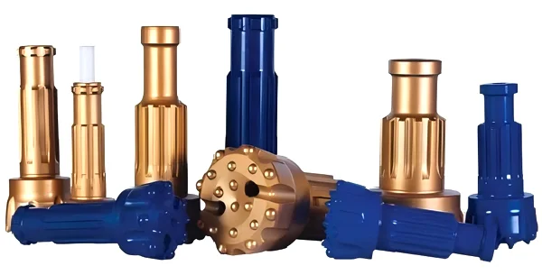
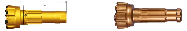
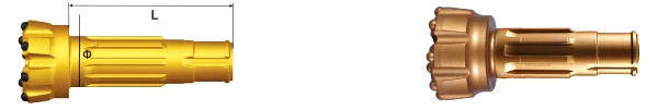
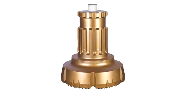
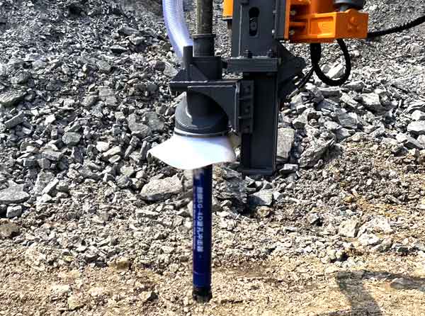
DTH (down-the-hole) drilling involves a drilling hammer at the bottom of a drill string, the hammer is powered by compressed air transmitted via drilling rod to drive piston and produce impact power, which is then delivered into rocks for drilling and crushing. DTH drilling can be applied in mining, quarrying, water well drilling, foundation piling, etc.
1.Enhanced fatigue strength through advanced forging technology.
2.High quality carbide in optimal sizes for stable longevity.
3.Precision inlaying technology prevents carbide detachment.
4.State of the art heat treatment ensures superior hardness and wear resistance.
5.Tailored design and specialized processing for extended service life across various rock formations.

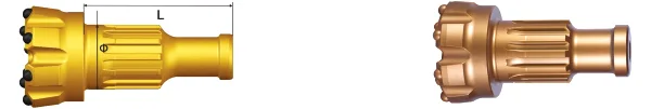
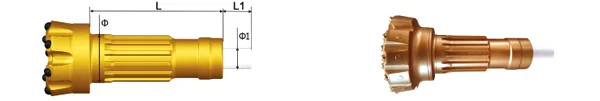
DHD Shank
| Model | Bit shank | L | φ | Spline | Air hole | Rec.hole size(mm) |
| JS3.5B | BR33 | 165 | 54 | 7 | 2 | 90-105 |
| JS3.5D | DHD3.5 | 181 | 54.6 | 8 | 2 | 90-105 |
| JS4H | DHD340 | 209 | 65 | 8 | 2 | 105-130 |
| JS5H | DHD350 | 260 | 84 | 8 | 2 | 140-152 |
| JS6H | DHD360 | 308 | 101.5 | 8 | 2 | 152-190 |
| JS8H | DHD380 | 350 | 128.5 | 10 | 2 | 203-245 |
| TSK12H | DHD112 | 490 | 183 | 8 | 3 | 305-380 |
SD Shank
| Model | Bit shank | L | φ | Spline | Air hole | Rec.hole size(mm) |
| JS4S | SD4 | 260 | 67 | 8 | 2 | 105-130 |
| JS5S | SD5 | 258 | 82.5 | 8 | 2 | 140-152 |
| JS6S | SD6 | 324 | 102 | 8 | 2 | 152-190 |
| JS8S | SD8 | 321 | 118 | 8 | 2 | 203-245 |
| JS10S | SD10 | 355.8 | 164.5 | 8 | 2 | 245-305 |
| JSK12S | SD12 | 470 | 185.5 | 8 | 3 | 305-380 |
MISSION Shank
| Model | Bit shank | L | φ | Spline | Air hole | Rec.hole size(mm) |
| JS3.5M | MISSION35 | 225 | 55 | 8 | 2 | 90-105 |
| JS4M | MISSION40 | 228 | 68 | 12 | 2 | 105-130 |
| JS5M | MISSION50 | 260 | 82.5 | 12 | 2 | 140-152 |
| JS6M | MISSION60 | 231 | 106.5 | 12 | 2 | 152-190 |
| JS8M | MISSION80 | 329 | 128.5 | 12 | 2 | 203-245 |
QL Shank
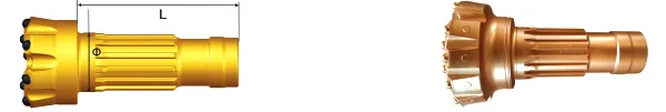
| Model | Bit shank | L | φ | Spline | Air hole | Rec.hole size(mm) |
| JS4X | QLX40 | 209.5 | 69 | 12 | 2 | 105-130 |
| JS5L | QL50 | 240 | 88.5 | 12 | 2 | 140-152 |
| JS6L | QL60 | 253 | 106 | 12 | 2 | 152-190 |
| JS8L | QL80 | 331 | 136 | 16 | 2 | 203-245 |
| TK12L | QL120 | 492 | 208.5 | 12 | 3 | 305-380 |
DHD Shank
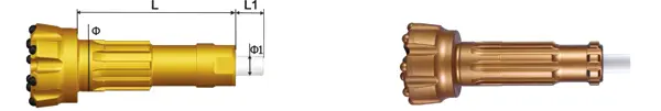
| Model | Bit shank | L | 中 | L1 | φ1 | Spline | Air hole | Rec.hole size(mm) |
| JH3.5D | DHD3.5 | 181 | 54.6 | 54.6 | 24.5 | 8 | 2 | 90-105 |
| JH4H | DHD340 | 209 | 65 | 59 | 27 | 8 | 2 | 105-130 |
| JH5H | DHD350 | 260 | 84 | 56 | 35 | 8 | 2 | 140-152 |
| JH6H | DHD360 | 308 | 101.5 | 55 | 38 | 8 | 2 | 152-190 |
| JH8H | DHD380 | 350 | 128.5 | 51 | 50.6 | 10 | 2 | 203-245 |
| JK12H | DHD112 | 490 | 183 | 52.2 | 63.2 | 8 | 3 | 305-380 |
SD Shank
| Model | Bit shank | L | 中 | L1 | φ1 | Spline | Air hole | Rec.hole size(mm) |
| JH4S | SD4 | 260 | 67 | 54 | 26 | 8 | 2 | 105-130 |
| JH5S | SD5 | 258 | 82.5 | 54.5 | 32 | 8 | 2 | 140-152 |
| JH6S | SD6 | 324 | 102 | 53 | 36.4 | 8 | 2 | 152-190 |
| JH8S | SD8 | 321 | 118 | 57 | 41 | 8 | 2 | 203-245 |
| JH10S | SD10 | 355.8 | 164.5 | 60.3 | 56 | 8 | 3 | 245-305 |
| JK12S | SD12 | 470 | 185.5 | 48 | 63.2 | 8 | 3 | 305-380 |
QL Shank
| Model | Bit shank | L | φ | L1 | φ1 | Spline | Air hole | Rec.hole size(mm) |
| JH4X | QLX40 | 209.5 | 69 | 58 | 32.2 | 12 | 2 | 105-130 |
| JH5L | QL50 | 240 | 88.5 | 52 | 38.5 | 12 | 2 | 140-152 |
| JH6L | QL60 | 253 | 106 | 59 | 46 | 12 | 2 | 152-190 |
| JH8L | QL80 | 331 | 136 | 54 | 54.6 | 16 | 2 | 203-245 |
| TK12L | QL120 | 492 | 208.5 | 52.2 | 71.5 | 12 | 3 | 305-380 |
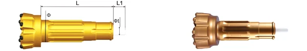
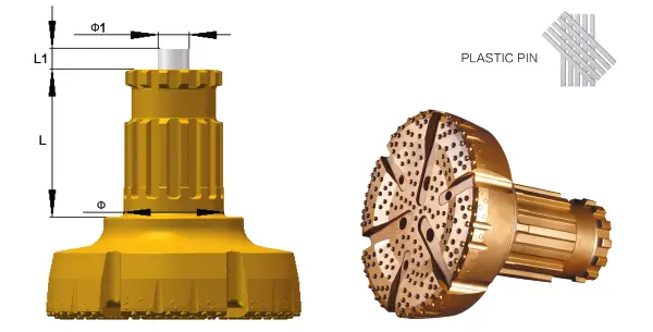
Features
◆Military grade special steel minimizes breakage and cracking failures.
◆Advanced forging process enhances the fatigue strength of the drill bit steel body.
◆Ultrasonic and magnetic particle flaw detection identify and eliminate material and forging defects, reducing potential quality issues during drilling.
◆Larger carbides extend the service life of the drill bit
◆CNC machining ensures precise dimensions of the drill bit.
◆Specially designed foot valve provides high strength and toughness, ensuring reliable performance.
◆Shock absorbing plastic pin enhances the service life of the shank spline.
NumaShank
| Model | Bit shank | L | φ | L1 | φ1 | Spline | Air hole | Rec.hole size(mm) |
| JH10N | NUMA100 | 375 | 165 | 53 | 54 | 10 | 3 | 245-305 |
| TK12N | Numa120 | 490.5 | 191 | 56.5 | 75.6 | 12 | 3 | 305-380 |
| TK12HN | Numa125 | 491 | 209 | 54 | 74.5 | 10 | 3 | 305-380 |
| TK14 | TK14 | 520 | 235 | / | / | 10 | 3 | 400-500 |
| TK18 | NUMA180 | 527.5 | 297 | 80.7 | 93.2 | 12 | 6 | 500-600 |
| TK24 | TK24 | 560 | 380 | 80 | 118.2 | 14 | 6 | 600-800 |
| TK28 | TK28 | 560 | 430 | 80 | 118.2 | 16 | 6 | 800-1150 |
The optimum range of hole size for blast hole drilling with DTH is 90 mm to 254 mm (3 ½”–10″). Smaller blast holes are generally drilled using tophammer, and larger holes generally use rotary machines.
In other applications, like foundation drilling, DTH hammers can be used with single bit in hole sizes up to . 750 mm (30″). With multiple hammer units CD (Cluster drills) drill holes up to 70″ or 1778 mm.
As a rule of thumb, the smallest hole diameter a DTH hammer can drill is its nominal size. A 4 inch hammer will drill a 4 inch (102 mm) hole. The limiting factor is the outside diameter of the hammer, because, as hole diameter reduces, airflow is restricted. Maximum hole size for production drilling is the nominal hammer size plus 1 inch, so for a 4 inch hammer the maximum hole size is 5 inch (127–130 mm).
Choosing the right hammer is largely determined by hole size and type of rock formation. Ideally, the size of the hammer should match the required hole dimension as closely as possible, leaving just enough space for cuttings to evacuate the hole.
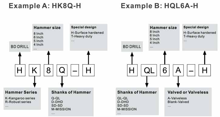
Product codes are a valuable tool to describe and identify the product. In the code structure we have tried to describe the product features with an alphanumeric system and not always 100% logical, but with the attached key you will be able to find the product you are looking for or alternative products.
| Hammer | BR2A | DHD3.5 | HK4D | HD45 | HQL4A | HQL50 | HK5Q | HD55 | HQL60 | HQL6A | HQL80 | HD85 | HK9Q | HSD10 | HSD12 | HK12Y | N125-R |
|---|---|---|---|---|---|---|---|---|---|---|---|---|---|---|---|---|---|
| Recommended bit size, mm | 76 | 92-105 | 112-127 | 140-152 | 165-178 | 203-229 | 216-229 | 245-305 | 305-445 | 305-350 | 305-445 | ||||||
| Bit Shank | BR2A | DHD3.5 | DHD340A | QL40 | QL50 | DHD350 | QL60 | QL80 | DHD380 | QL80 | SD10 | SD12 | HY12 | NUMA125R | |||
| External diameter, mm | 63 | 82 | 100 | 100 | 101 | 126.5 | 127.5 | 126.5 | 148 | 146 | 185 | 185 | 203 | 225 | 275 | 275 | 275 |
| Length excl. thread, mm (Less bit) | 837 | 855 | 915 | 1032.5 | 1057 | 1147 | 935 | 1167 | 1121 | 1182 | 1471 | 1487 | 1345 | 1413 | 1680 | 1590 | 1812 |
| Hammer weight, kg (Less bit) | 14.1 | 25 | 37.5 | 40.6 | 41 | 71.6 | 67.6 | 77.2 | 105 | 105 | 203 | 206 | 228 | 303 | 526 | 510.2 | 546 |
| Package case size | (L)910 (W)90 (H)120 | (L)1200 (W)110 (H)140 | (L)1010 (W)130 (H)160 | (L)1080 (W)125 (H)134 | (L)1150 (W)130 (H)160 | (L)1290 (W)150 (H)175 | (L)1100 (W)155 (H)180 | (L)1290 (W)150 (H)175 | (L)1270 (W)170 (H)200 | (L)1260 (W)180 (H)200 | (L)1440 (W)230 (H)270 | (L)1560 (W)230 (H)270 | (L)1500 (W)240 (H)280 | (L)1620 (W)275 (H)290 | (L)1880 (W)320 (H)320 | (L)1665 (W)320 (H)360 | (L)1880 (W)310 (H)310 |
| Top Sub thread | RD50 | 2-3/8″ API REG | 3-1/2″ API REG | 4-1/2″ API REG | 6-5/8″ API REG | 6-5/8″ API REG 7-5/8″ API REG | 6-5/8″ API REG | ||||||||||
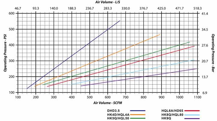
| Working Pressure, PSI | 80-170 | 150-250 | 200-300 | 250-350 | 300-350 | 300-380 | 300-380 | 150-350 | 200-350 | ||||||||
| Air consumption, CFM | 250-350 | 300-400 | 500-700 | 500-800 | 600-900 | 950-1200 | 950-1200 | 1000-1800 | 1200-1500 | 800-1800 | |||||||
| Piston diameter, mm | 42.7 | 65 | 82 | 80 | 80 | 104 | 102 | 100 | 122 | 121 | 150 | 150 | 165 | 185 | 225 | ||
| Piston weight, kg | 1.7 | 5.1 | 9.2 | 9 | 9 | 17 | 17 | 16 | 24 | 24 | 38 | 42 | 50 | 68 | 110 | 111 | 111 |
| Wrench flat, mm | L47 W50 | L57 W35 | L74.5 W45 | L64 W40 | NO wrench flat | L89 W60 | L88 W50 | L89 W60 | L101 W65 | L101 W60 | L128 W70 | L140 W70 | L128 W70 | L140 W70 | L140 W70 | L140 W70 | L140 L70 |
| Feed force, kN | 2~6 | 3~8 | 5~15 | 6~25 | 7~20 | 10~25 | 15~30 | 20~35 | |||||||||
| Rotation speed, r/min | 30-70 | 3-90 | 25-80 | 20-70 | 25-60 | 20-60 | 15-35 | ||||||||||
| Drilling conditions and project specifications may require larger air package to be used | |||||||||||||||||
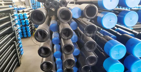
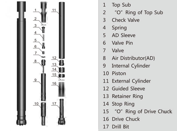
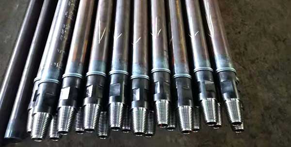
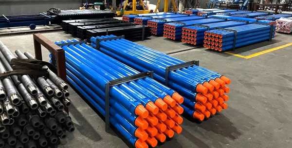
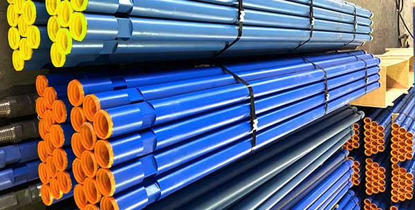
The DTH drill pipe consist of pipe and two adapters, box and pin. We use high strength and well-resistance alloy steel, inserting of high tensile seamless pipe, and according to different drilling depth, we can offer various thickness of pipe and material for customers’requirements.
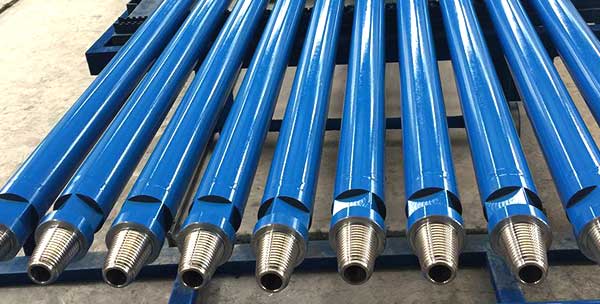
DTH drill pipe Feature
• Diameter: 76mm, 89mm, 102mm, 114mm, 127mm, 140mm
• Length: 1000mm, 1500mm, 2000mm, 3000mm, 5000mm, 6000mm
• Thread: 2 3/8’’ API REG, 2 7/8’’ API REG, 3 1/2’’ API REG, 4 1/2’’ API REG,2 3/8″ API IF, 3 1/2″ API IF; BECO 6”, BECO 8”
• Wall thickness: 5.5mm/6.5mm/7.5mm/8.5mm/10mm
• Other spaecial size can be customized by customer’s drawing.
• Advanced heat treatment technology and friction welding mahcine.
| Rod dia | Rod length | Thickness | Connect thread | Wrench flats | |
| (inch) | (mm) | (mm) | (mm) | (mm) | |
| 3 | 76 | 1000-6000 | 5 | API2 3/8”REG | 57/64.5 |
| 3 | 76 | 1000-9000 | 8 | API2 3/8”REG | 57/64.5 |
| 3 1/2 | 89 | 1000-6000 | 6 | API2 3/8”REG | 70/64 |
| 3 1/2 | 89 | 1000-9600 | 8 | API2 3/8”REG | 70/64 |
| 4 | 102 | 1000-9000 | 10 | API2 3/7”REG | 76/89 |
| 4 1/2 | 114 | 1500-7620 | 6 | API3 1/2”REG | 89/95 |
| 4 1/2 | 114 | 1500-9140 | 8 | API3 1/2”REG | 89/95 |
| 4 1/2 | 114 | 1500-9140 | 10 | API3 1/2”REG | 89/95 |
| 4 1/2 | 114 | 1500-9140 | 18 | API3 1/2”REG | 89/95 |
| 5 | 127 | 1500-9500 | 12 | API3 1/2”REG | 89 |
| 5 | 127 | 1500-9500 | 14 | API3 1/2”REG | 89 |
| 5 | 127 | 1500-9500 | 18 | API3 1/2”REG | 89 |
| 5 1/2 | 140 | 1500-9500 | 9 | API4 1/2”REG or 4’FH | 114 |
| 5 1/2 | 140 | 1500-9500 | 10 | API4 1/2”REG or 4’FH | 114 |
| 5 1/2 | 140 | 1500-9500 | 12 | API4 1/2”REG or 4’FH | 114 |