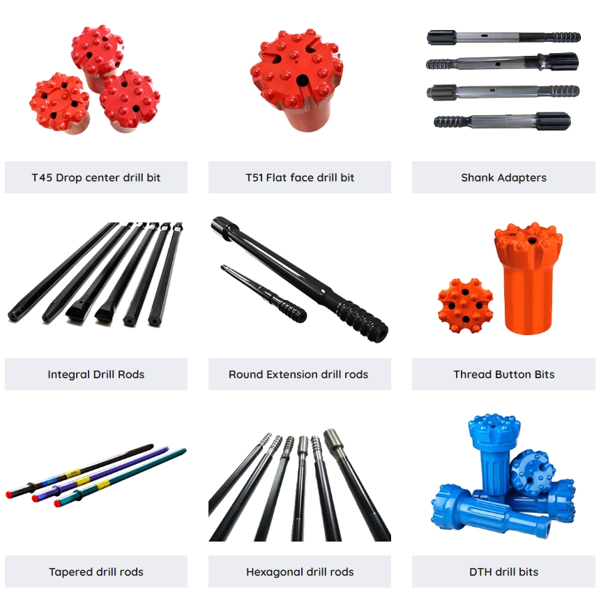
“Round Extension Drill Rod Drift Rod” usually refers to a tool used for geological exploration, drilling, or other similar applications. This tool is widely produced and supplied in China, as China’s manufacturing industry enjoys a high reputation worldwide.
Here are some possible features of this product and factors to consider when purchasing:
Quality: Chinese manufacturers are able to produce high-quality products, but there are also many products with varying quality in the market. Therefore, choosing reputable suppliers and brands is very important.
Specifications: These drill rods typically come in multiple sizes to meet the needs of different applications. Before purchasing, please make sure you know the required length, diameter, and other relevant specifications.
Material: Drill pipes are usually made of high-strength steel or other alloys to ensure sufficient durability and strength under harsh working conditions.
Price: Chinese manufacturers are usually able to offer products at more competitive prices, but please note that price should not be the only factor to consider. Factors such as quality, service, and delivery time are equally important.
Service: Some suppliers may provide additional services such as customized design, fast delivery, or after-sales support. These services may be very valuable for your project.
When using Mf T45 1220mm Extension Drill Rods (or any other type of extended drill rod) for drilling, ensuring the safety and efficiency of the operation is crucial. Here are some key considerations:
Equipment inspection:
Before use, carefully inspect the drill pipe for cracks, wear, or deformation.
Check if the connecting part of the drill pipe is intact, ensuring that the connection is firm and not loose.
Check the connection between the drill bit and drill pipe to ensure they match and are tightened.
Safety equipment:
Wear appropriate protective clothing, such as safety shoes, gloves, goggles, etc.
If there is noise pollution in the work environment, please wear earplugs or earmuffs.
If working at heights is required, please ensure the use of safety belts and other high-altitude work safety equipment.
Operating specifications:
When operating drill pipes, follow the manufacturer’s operating instructions and safety manual.
Maintain the drill pipe at a vertical or predetermined angle to avoid operating on unstable or uneven ground.
Use appropriate torque and speed to avoid excessive force or rapid rotation.
Maintenance:
Regularly clean the drill pipe to remove soil, oil, and other impurities.
Check and replace worn components such as drill bits, bearings, etc.
When storing drill pipes, ensure they are dry, dust-free, and avoid excessive stacking.
Environmental factors:
When operating in damp or humid environments, pay attention to moisture and corrosion prevention.
Check if the performance of the drill pipe is affected under extreme temperature conditions.
Avoid operating in flammable or explosive environments and ensure that there are no combustibles around.
Emergency situation handling:
During the operation, if the drill pipe gets stuck, breaks or experiences other abnormal situations, please stop the operation immediately and seek professional assistance.
Familiarize oneself with the emergency stop button or switch of the equipment and take prompt action when necessary.
Training and Education:
Ensure that operators receive appropriate training and understand the operation and maintenance requirements of the equipment.
Regularly organize safety meetings and training courses to enhance employee safety awareness and operational skills.
Compliance with regulations:
Comply with local regulations and standards to ensure that operations comply with safety regulations.
Before carrying out any work, understand and comply with relevant environmental and waste disposal regulations.
Recording and reporting:
Record the usage, maintenance records, and any abnormal situations of the equipment.
If necessary, report any safety issues or potential risks to relevant departments or management personnel.
By following these precautions, you can use the Mf T45 1220mm Extension Drill Rods for drilling operations more safely and effectively.
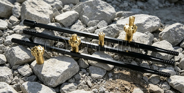
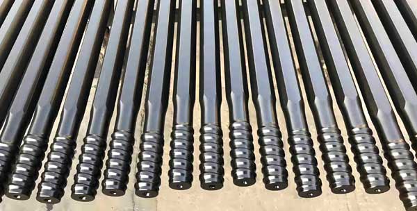
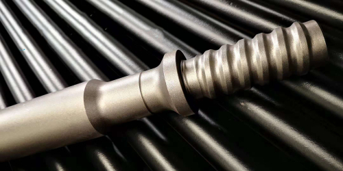
The extended drill rod of a rock drill is a special type of drill rod used on a rock drill (also known as a drilling rig or rock drill) to increase the drilling depth when drilling in rocks, concrete, or other hard materials. Extended drill rods are usually made of high-strength alloy steel, which has sufficient strength and durability to cope with harsh drilling environments.
Here are some detailed information about extending the drill rod of a rock drill:
Materials: Extended drill rods are usually made of high-strength alloy steel, such as 4340 steel, 30CrMnSiA, etc. These materials have high yield strength and tensile strength, and can withstand high torque and high pressure during the drilling process.
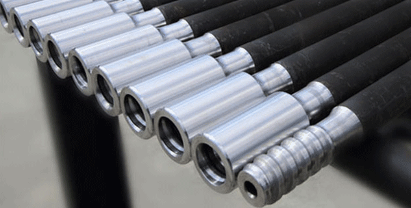
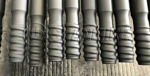
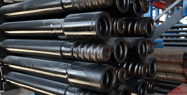
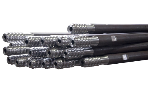
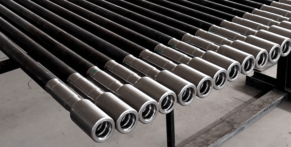
Structural design: The design of an extended drill pipe typically includes a threaded male joint and a threaded female joint for connection with other drill pipes or drill bits. These joints usually use special connection mechanisms, such as spiral locking or conical locking, to ensure that they do not fall off during the drilling process.
Length: The length of the extended drill pipe can be customized according to needs, with common lengths ranging from 1 meter to several meters. The choice of appropriate length depends on specific drilling requirements, such as drilling depth, rock hardness, etc.
Diameter: The diameter of the extended drill pipe is also determined according to specific needs, with common diameters ranging from 32mm to 115mm. Choosing the appropriate diameter can ensure compatibility between the drill pipe and the drill bit, and optimize the drilling effect.
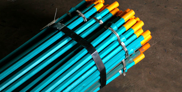
Surface treatment: In order to improve the wear resistance and corrosion resistance of drill pipes, some extended drill pipe surfaces will undergo special treatment, such as sandblasting, painting, or coating.
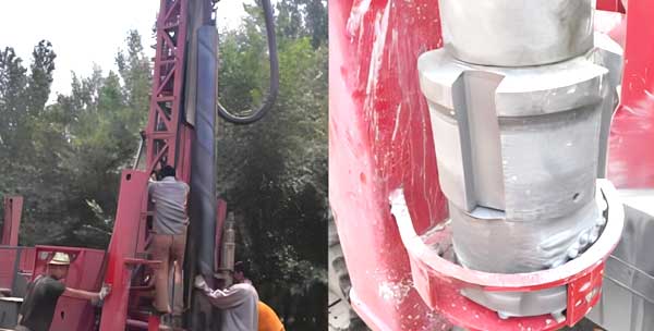
Safety precautions: When using extended drill rods, it is necessary to ensure compatibility with the rock drill and other accessories, and to install and use them correctly according to the operating manual. In addition, it is also necessary to pay attention to keeping the drill pipe clean and lubricated to extend its service life.
Application areas: The extended drill rods of rock drills are widely used in mining, tunnel construction, basic engineering, geological exploration and other fields. They can be used to drill holes of different diameters and depths to meet various engineering needs.
In short, extending the drill rod of a rock drill is an important drilling tool, which is of great significance for improving drilling efficiency and effectiveness. When selecting and using extended drill rods, it is necessary to comprehensively consider specific needs and pay attention to following relevant safety operating procedures.
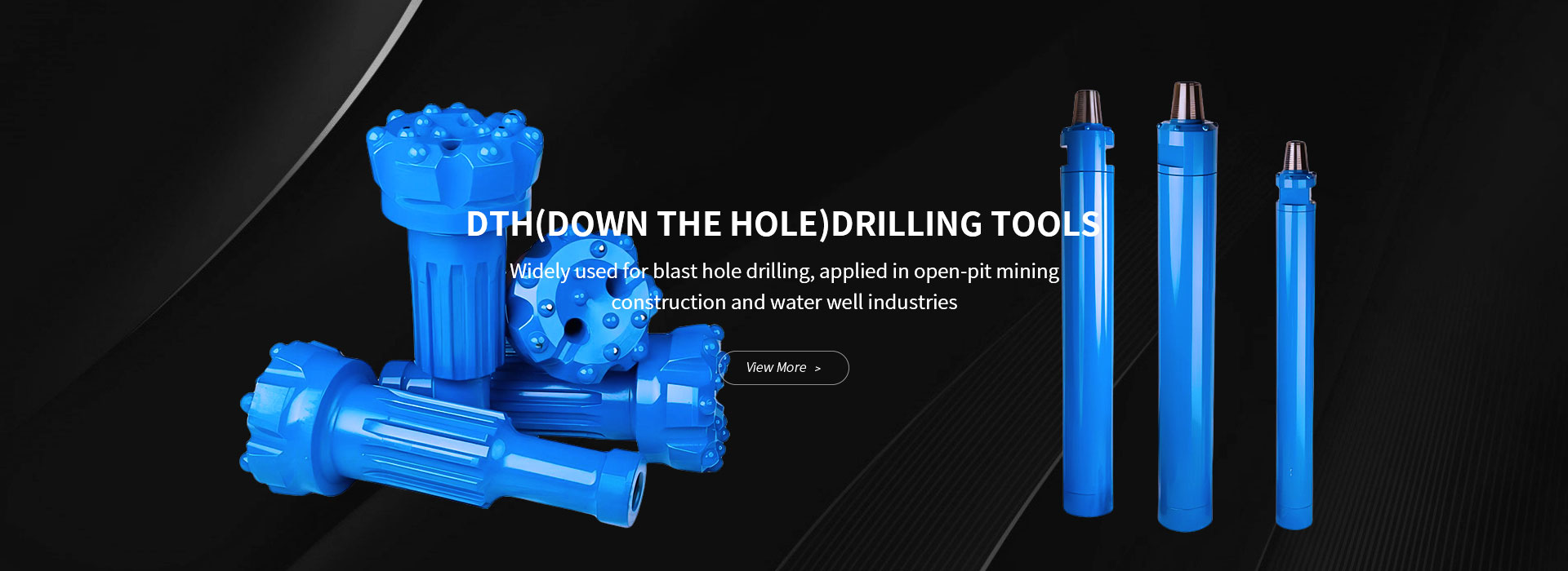
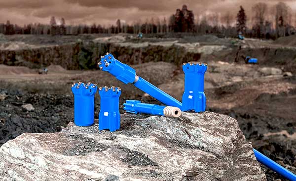
DHD360 165 DTH Bit (Down The Hole Bit) typically has the following characteristics:
Efficient crushing performance: The DHD360 165 DTH Bit is designed to achieve efficient crushing performance in hard rocks. Its unique cutting structure and impact design can quickly and effectively break rocks, improving drilling efficiency.
High strength and durability: Drill bits are usually made of high-strength alloy steel and can withstand high-frequency impacts and rotations, ensuring long-term stable operation under harsh working conditions.
Adaptability: This type of drill bit design usually takes into account multiple rock types and geological conditions, and has a wide range of adaptability. Both soft and hard rocks can ensure the smooth progress of drilling to a certain extent.
Good thermal stability: Under high-speed rotation and high-frequency impact working conditions, the drill bit will generate a large amount of heat. DHD360 165 DTH Bit usually has good thermal stability, which can effectively prevent performance degradation or damage caused by overheating.
Easy to replace and maintain: In order to facilitate maintenance and replacement, this type of drill bit is usually designed with an easy to operate connecting mechanism, which can be quickly removed from the drilling rig and replaced or repaired.
Accurate size control: Accurate control of drill bit diameter and length is crucial for ensuring the accuracy and quality of drilling. DHD360 165 DTH Bit typically has strict dimensional tolerance control to ensure accuracy and consistency in drilling.
Environmental friendliness: With the increasing awareness of environmental protection, modern DTH drill bits are also paying more attention to environmental performance. They may use more environmentally friendly materials and manufacturing processes to reduce their impact on the environment.
DHD360 165 DTH Bit refers to a specific model of DTH (Down The Hole) drill bit. DTH drill bit is a tool specifically used for underground drilling, which breaks rocks through high-frequency impact and rotation for drilling operations.
In the DHD360 165 model, “DHD360” may represent the identifier of the manufacturer or product series, while “165” may represent a certain specification or size of the drill bit, such as diameter size. However, specific parameters and characteristics may vary depending on the manufacturer and actual application environment.
DTH drill bits are commonly used in fields such as mining, geological exploration, and construction, and can perform efficient drilling operations in hard geological conditions. They have the characteristics of high efficiency, durability, and strong adaptability, and can cope with different types and conditions of geological environments.
DHD360 165 DTH Bit (Down The Hole Bit) typically has the following characteristics:
Efficient crushing performance: The DHD360 165 DTH Bit is designed to achieve efficient crushing performance in hard rocks. Its unique cutting structure and impact design can quickly and effectively break rocks, improving drilling efficiency.
High strength and durability: Drill bits are usually made of high-strength alloy steel and can withstand high-frequency impacts and rotations, ensuring long-term stable operation under harsh working conditions.
Adaptability: This type of drill bit design usually takes into account multiple rock types and geological conditions, and has a wide range of adaptability. Both soft and hard rocks can ensure the smooth progress of drilling to a certain extent.
Good thermal stability: Under high-speed rotation and high-frequency impact working conditions, the drill bit will generate a large amount of heat. DHD360 165 DTH Bit usually has good thermal stability, which can effectively prevent performance degradation or damage caused by overheating.
Easy to replace and maintain: In order to facilitate maintenance and replacement, this type of drill bit is usually designed with an easy to operate connecting mechanism, which can be quickly removed from the drilling rig and replaced or repaired.
Accurate size control: Accurate control of drill bit diameter and length is crucial for ensuring the accuracy and quality of drilling. DHD360 165 DTH Bit typically has strict dimensional tolerance control to ensure accuracy and consistency in drilling.
Environmental friendliness: With the increasing awareness of environmental protection, modern DTH drill bits are also paying more attention to environmental performance. They may use more environmentally friendly materials and manufacturing processes to reduce their impact on the environment.
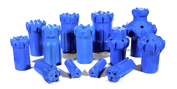
Product description: Ball button drill bit
Drill bit type: X-shaped drill bit (solid center)
Diameter: 41mm (i.e. 1-5/8 inches)
Product number: 90510207
Product codes: 102-5041-56, 39-20
Number of buttons: 7
Button specification: Button diameter (mm) information not provided, but button arrangement is: 4 outer rings x 9mm, 2 center x 9mm
Flushing holes: 2 on the side and 1 on the center
Approximately weight: 0.6kg
Thread type: R25
Steel grade: 50R61
Carbide grade: BH30
This spherical button drill bit, with its X-shaped design and solid center structure, ensures high efficiency and stability in hard rock drilling. Its diameter and button layout are designed specifically for specific drilling tasks and are suitable for use in various rock types. In addition, the selection of steel and carbide grades further ensures the durability and cutting performance of the drill bit.
T38 Rock Drill Bit with Rope Thread x Button Bit is a type of drill bit specifically designed for rock drilling applications. The “T38” refers to the thread size, which is a standard thread size used in rock drilling equipment. The “Rope Thread” indicates that the bit has a threaded connection that allows it to be attached to a drill rod using a rope thread system. The “Button Bit” refers to the design of the cutting face, which typically has raised buttons or teeth that are used to cut into the rock.
This type of drill bit is commonly used in mining, quarrying, and other applications where hard rock needs to be drilled. The rope thread connection allows for easy attachment and detachment of the bit from the drill rod, while the button design provides efficient cutting and drilling performance.
When selecting and using a T38 rock drill bit with rope thread and button design, it is important to ensure that the bit is compatible with your specific drilling equipment and that it is properly maintained and used according to the manufacturer’s instructions. Regular inspection and replacement of worn parts, such as cutting teeth or button tips, is also important to maintain optimal drilling performance.
Bench and long-hole drilling using T51 drill rods with a diameter of 2″ (50.8 mm) are common practices in mining, quarrying, and similar industries. Here are some key points about T51 drill rods and their use in these applications:
Remember, the specific requirements and recommendations for drill rods may vary depending on the manufacturer, the type of rock being drilled, and the specific needs of the drilling operation. Always consult with the manufacturer or a qualified drilling expert for more information.
The H22*108 Tapered Drill Rod Z708 is a precision-engineered tool designed for various drilling applications. Here is a detailed description of its specifications and features:
Product Name: H22*108 Tapered Drill Rod Z708
Manufacturer: Atlas
Diameter: The initial diameter of the drill rod is H22, indicating a specific metric or imperial size that is suitable for the intended application. However, since it is a tapered drill rod, the diameter gradually decreases from one end to the other.
Length: The drill rod is 108 units long, typically in millimeters or inches, depending on the manufacturer’s specifications. This length allows for deep drilling operations or for reaching into tight spaces.
Material: The Z708 drill rod is made from high-grade steel or a similar alloy that provides durability, strength, and resistance to wear and tear. This material ensures that the drill rod can withstand the forces and temperatures encountered during drilling operations.
Tapered Design: The tapered shape of the drill rod allows for gradual enlargement of the hole diameter as the drill progresses. This design is beneficial in applications where a stepped or variable-diameter hole is required. The taper angle and rate of diameter change are carefully controlled to ensure accurate hole sizes and smooth drilling.
Applications: The H22*108 Tapered Drill Rod Z708 is suitable for a wide range of drilling applications, including construction, manufacturing, and machining. It can be used with hand-held drills, drill presses, or CNC machines to create precise holes in various materials such as metal, plastic, wood, and composites.
Advantages: The Z708 drill rod offers several advantages, including its high-grade material, precision engineering, and tapered design. It is capable of achieving accurate hole sizes and smooth finishes, while also resisting breakage and wear during prolonged use.
Overall, the H22*108 Tapered Drill Rod Z708 is a reliable and versatile tool that is suitable for a wide range of drilling applications. Its precision-engineered design and high-grade material ensure durability and accuracy, making it a valuable addition to any workshop or toolbox.
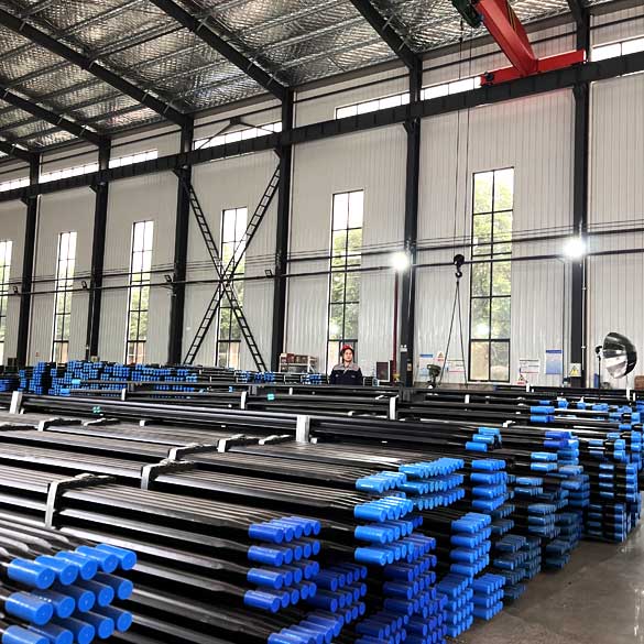
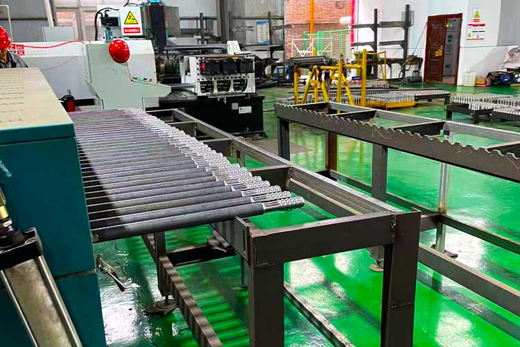
Shandike can produce matching drilling tools
“T38 drill rod” likely refers to a specific type or specification of drill rod, where “T38” might represent a particular diameter, strength, or material grade. However, since “T38” is not a universally recognized or standardized term, its exact meaning would require reference to specific industry standards or manufacturer specifications.
“Taphole Drill Rod” is a specialized drill rod used primarily for drilling and cleaning operations in the tap hole of a blast furnace. This type of drill rod is required to endure harsh environments such as high temperatures, high pressures, and mechanical impacts. Therefore, its materials, design, and manufacturing process have specific requirements.
Generally, these two types of drill rods may differ in materials, manufacturing processes, and application scenarios. If you require more specific information, it is recommended to refer to relevant industry standards, technical specifications, or consult with professional manufacturers.
China’s Expertise in Manufacturing T38 32mm and 38mm Rock Drilling Tools Hole Drill Rods
As the mining and construction industries continue to evolve, the demand for reliable and efficient rock drilling tools has grown exponentially. Among these tools, hole drill rods play a crucial role in ensuring the smooth progress of drilling operations. China, with its advanced manufacturing capabilities and expertise, has become a leading producer of high-quality T38 32mm and 38mm rock drilling tools hole drill rods.
I. Introduction to T38 32mm and 38mm Hole Drill Rods
T38 32mm and 38mm hole drill rods are specifically designed for rock drilling applications, where they are used to create precise holes in various rock formations. The T38 threading ensures compatibility with most rock drilling machines, while the 32mm and 38mm diameters allow for efficient material removal and faster drilling speeds.
II. Manufacturing Expertise in China
China’s manufacturing industry has made significant strides in the production of rock drilling tools, particularly in the field of hole drill rods. Here are some of the key factors that contribute to China’s expertise in manufacturing T38 32mm and 38mm hole drill rods:
III. Technical Specifications and Advantages
T38 32mm and 38mm hole drill rods manufactured in China offer several technical specifications and advantages that make them a preferred choice for rock drilling applications:
IV. Applications in Mining and Construction
T38 32mm and 38mm hole drill rods find widespread applications in the mining and construction industries, including:
V. Conclusion
China’s expertise in manufacturing T38 32mm and 38mm rock drilling tools hole drill rods has positioned it as a leading supplier to the global mining and construction industries. With their excellent strength, durability, and compatibility, these hole drill rods are essential for ensuring the smooth progress of drilling operations. As the demand for rock drilling tools continues to grow, China’s manufacturing capabilities will continue to play a crucial role in meeting the needs of this booming industry.
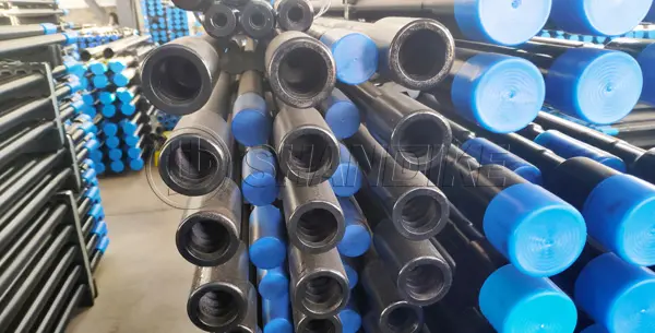
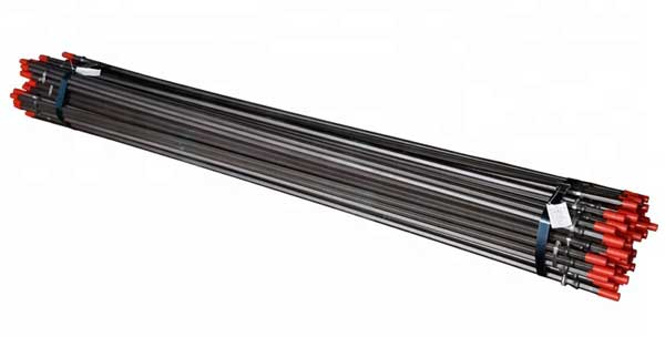
R38 T38 10ft extension drill rods are used in various drilling applications, especially in mining and construction. The “R38” and “T38” refer to the thread specifications of the drill rods, which are important for ensuring compatibility with drill machines and accessories.
These extension drill rods are typically made of high-strength steel and have a length of 10 feet (3.05 meters). They are designed to be connected to each other or to drill bits to extend the reach of the drilling equipment.
If you are considering purchasing or using R38 T38 10ft extension drill rods, it is important to ensure that they are compatible with your drill machine and that you have the necessary training and certification to operate the equipment safely. Additionally, always follow the manufacturer’s instructions and safety recommendations to prevent accidents and injuries.

When selecting drill steel and rock drill bits, the following key factors need to be considered:
Materials: The materials of drill bit steel and rock drill bits directly affect their wear resistance, hardness, and toughness. For example, high carbon steel has high hardness and wear resistance, making it suitable for drilling on hard rocks; Low carbon steel, on the other hand, has better toughness and is suitable for situations that require bending or deformation. Therefore, when choosing, it is necessary to choose suitable materials based on specific usage environments and needs.
Diameter: The diameter of the drill bit steel needs to be selected based on the required drilling diameter. Generally speaking, the diameter of the drill bit steel should be slightly larger than the required diameter of the borehole to ensure smooth drilling. Meanwhile, the diameter of rock drill bits also needs to be selected based on the hardness and density of the rock to ensure drilling efficiency and drill bit lifespan.
Length: The length of drill steel and rock drill bits needs to be selected based on specific working depth and requirements. Shorter drill bits are suitable for working in shallow holes, while longer drill bits are suitable for deep hole operations. When selecting, it is necessary to ensure that the length of the drill bit is long enough to achieve the required working depth.
Thread type: The thread type of drill bits for steel and rock can also affect their effectiveness. Common types of threads include straight threads, tapered threads, and spiral grooves. Straight thread drill bits are suitable for most rock types, while cone thread drill bits are more suitable for drilling on harder rocks. Spiral groove drills have better chip removal performance and are suitable for situations that require efficient chip removal.
Brand and quality: Choosing well-known brand drill steel and rock drill bits can ensure the quality and performance of the product. At the same time, when purchasing, it is necessary to pay attention to checking the appearance, size, and identification information of the product to ensure that it meets relevant standards and requirements.
In summary, when selecting drill steel and rock drill bits, it is necessary to choose suitable materials, diameters, lengths, thread types, brands, and quality based on specific usage environments and needs. At the same time, it is also necessary to pay attention to choosing legitimate channels to purchase products, in order to ensure their quality and performance.
The phrase described above is about a drill rod specifically designed for coal mining. Here’s the translation of the explanation into English:
In summary, the phrase described a hexagonal rock drilling rod with a specific taper and dimensions, specifically designed for coal mining applications. This type of drill rod plays a crucial role in coal mining operations, especially in drilling holes in rock strata.
The Hexagonal Steel B22 Rod 22mm Six-Edge Taper Drill Rod H22 Tunnel Drill Pipe is specifically designed for rock drilling in mining. Made of high-quality hollow hexagonal steel, it is sturdy, wear-resistant, efficient in debris removal, and easy to assemble and disassemble. The rod lengths range from 0.4 meters to 4 meters, and can be customized to meet specific drilling needs. The rods are connected using connecting sleeves to form a complete drilling system.
During the drilling process, this drill pipe effectively transports drilling mud to the drill bit and can be raised or lowered to adapt to different drilling requirements. Additionally, its tail can be equipped with various hydraulic roof bolt drills, and the head can be connected to various types of internal and external thread drill bits, ensuring smooth drilling operations.
Overall, the Hexagonal Steel B22 Rod 22mm Six-Edge Taper Drill Rod H22 Tunnel Drill Pipe is an efficient, durable, and easy-to-operate drilling tool widely used in mining, tunneling, and other engineering drilling applications. For more information about this product, please refer to the relevant product manual or consult professional drilling equipment suppliers.
Welcome to 28TH INTERNATIONAL EXHIBITION OF MACHINES AND EQUIPMENT FOR MINING, PROCESSING AND TRANSPORTATION OF MINERALS
Date:23 – 25 April 2024
location:Moscow, Crocus Expo, Pavilion 1
MiningWorld Russia is the an internationally-recognised trade show servicing the mining & mineral extraction industry. As a business platform, the exhibition connects equipment and technology manufacturers with buyers from Russian mining companies, mineral processors, and wholesalers interested in buying the latest mining solutions.
As a professional rock drilling tool manufacturer in China, Luoyang Shandike Machinery Equipment Co., Ltd. will participate in MiningWorld Russia 2024 with its products. Welcome to our booth.
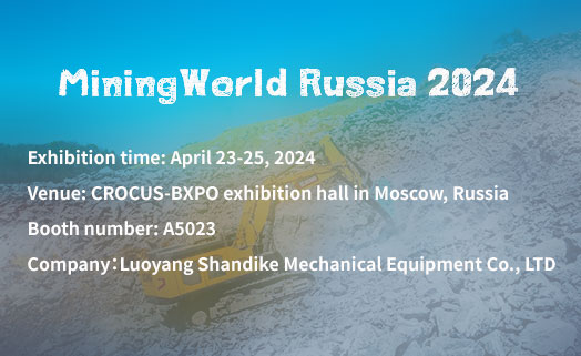
Exhibition time: April 23-25, 2024
Exhibition venue: CROCUS-BXPO exhibition hall in Moscow, Russia
Booth number: A5023
Company:Luoyang Shandike Machinery Equipment Co., Ltd