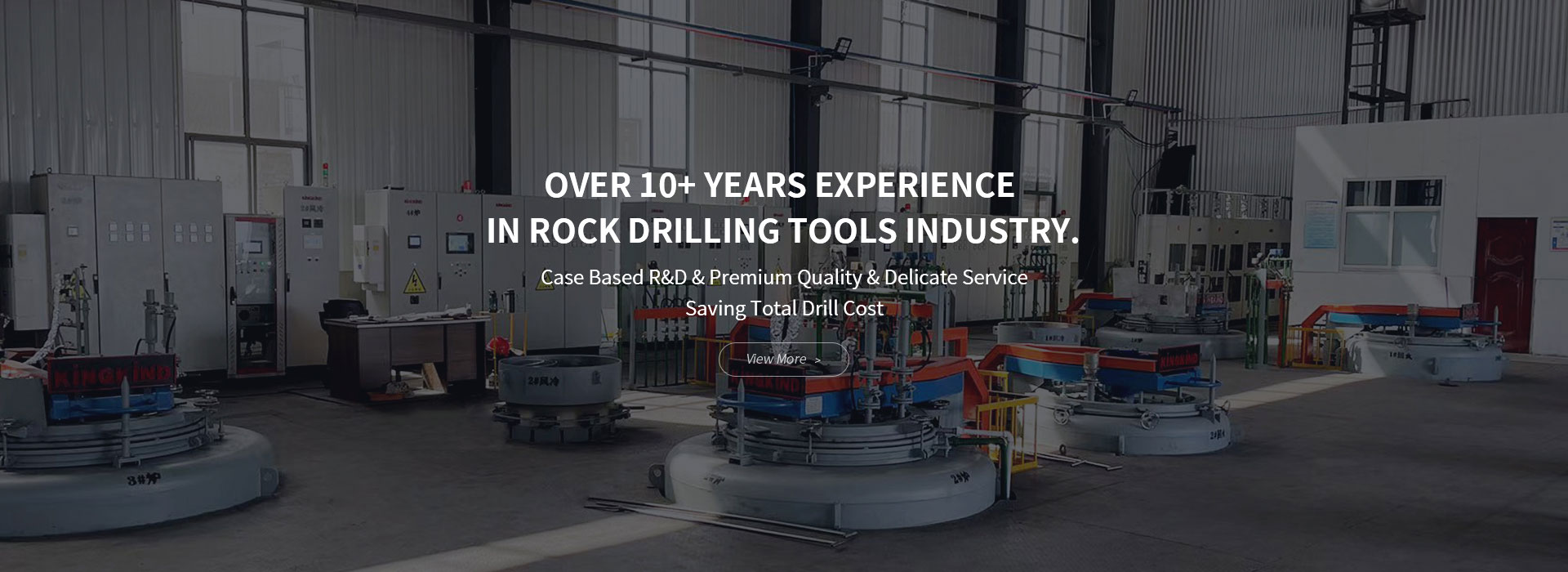
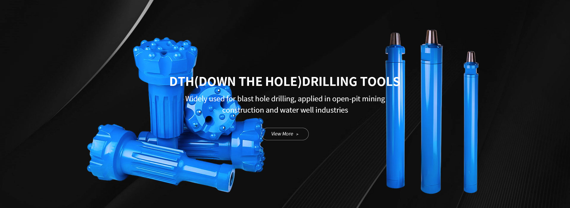
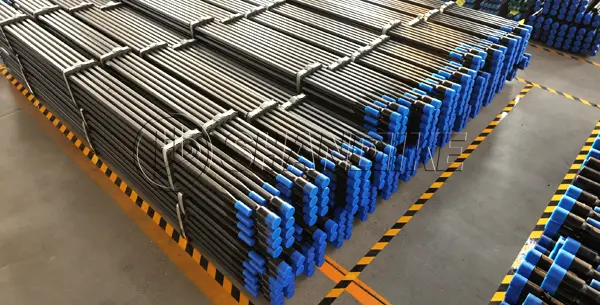
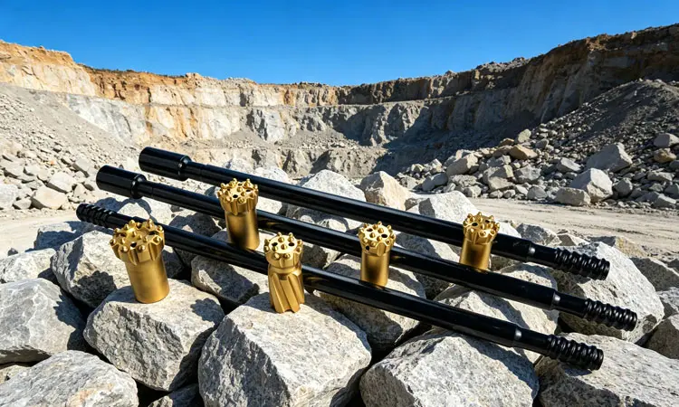
In the demanding worlds of mining, quarrying, and construction, efficiency is everything. The ability to drill faster, straighter, and with less downtime directly impacts the bottom line. At the heart of this process for many operations is a critical component: the top hammer drill rod.
This guide provides a comprehensive overview of top hammer drill rods, explaining what they are, how they work, and how to choose the right one for your project to optimize performance and reduce costs.
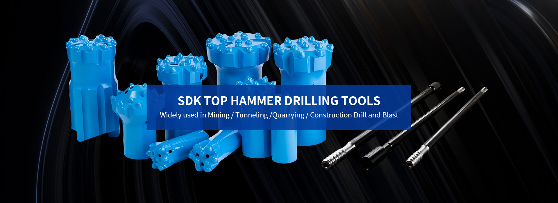
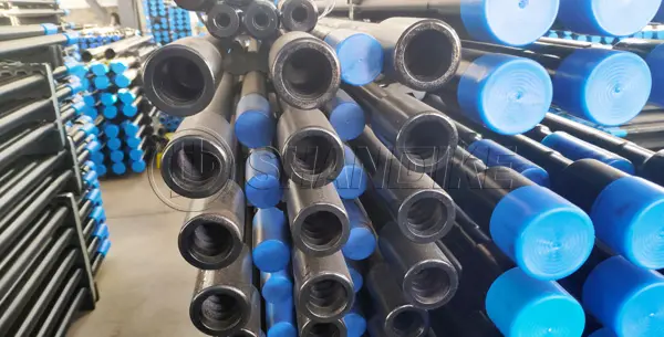
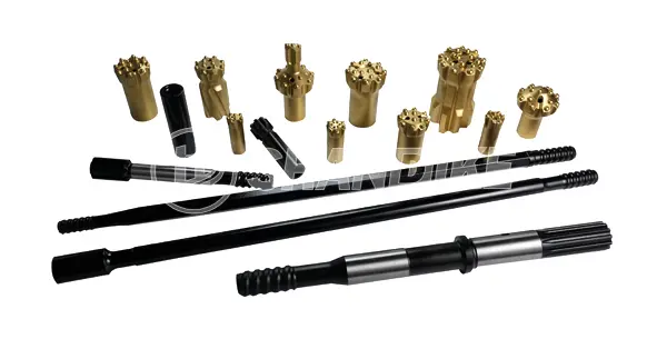
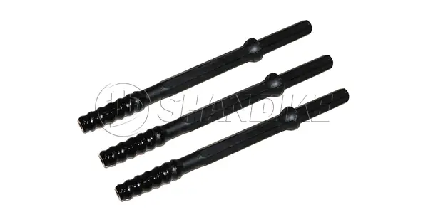
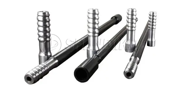
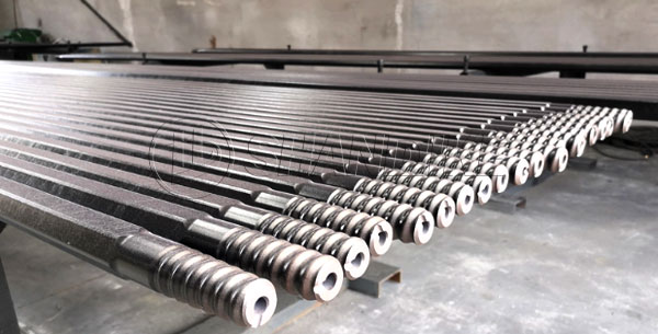
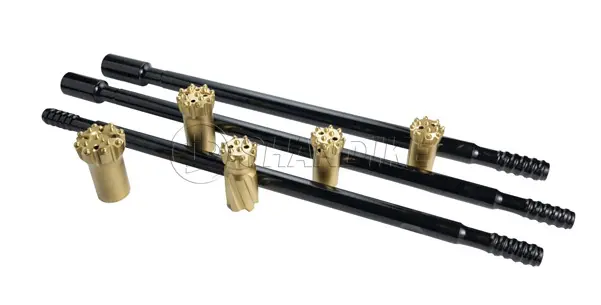
A top hammer drill rod is a key component of a top hammer drilling system. Its primary function is to efficiently transmit impact energy and rotational torque from the rock drill (the hammer) to the drill bit at the bottom of the hole.
The working principle is straightforward yet powerful: a piston in the rock drill delivers a percussive force, often 2,000 to 5,000 blows per minute, onto the shank adapter. This energy is then transferred through the drill rod to the bit, which fractures the rock. The rod also provides the necessary rotation to ensure the bit cuts into fresh rock and that the cuttings are flushed up and out of the hole.
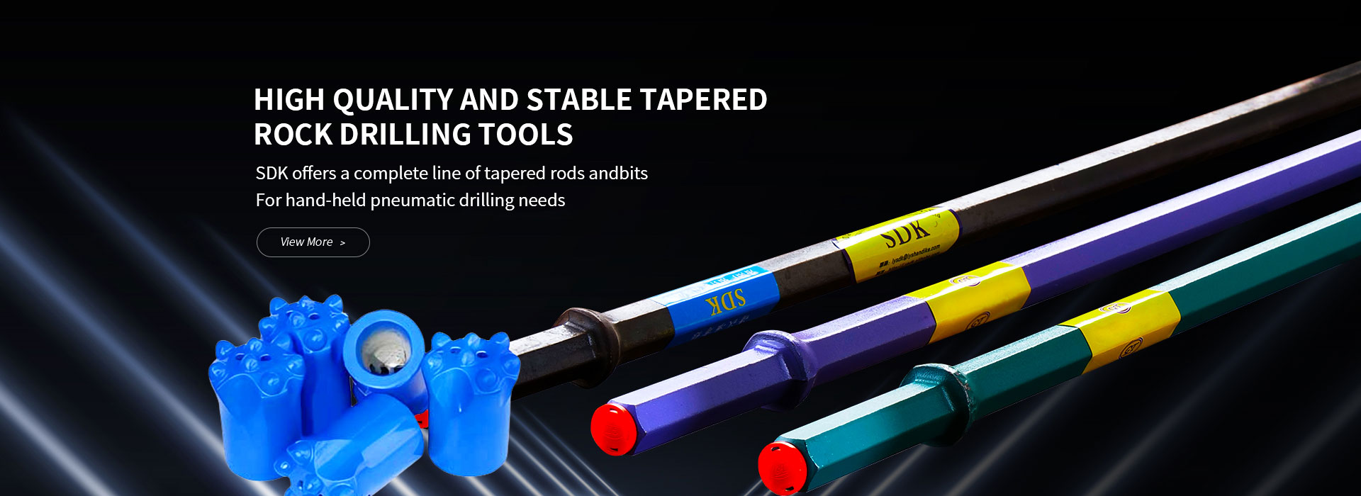
Selecting the right rod is crucial for success. The two most common types are MF (Male-Female) rods and Extension rods. Understanding their differences is key to making the right choice.
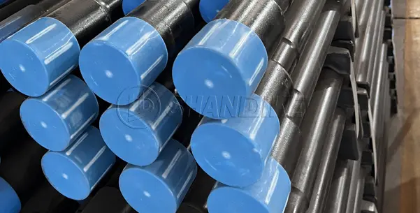
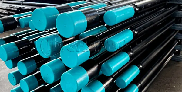
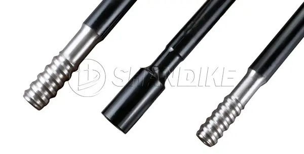
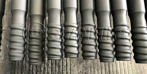
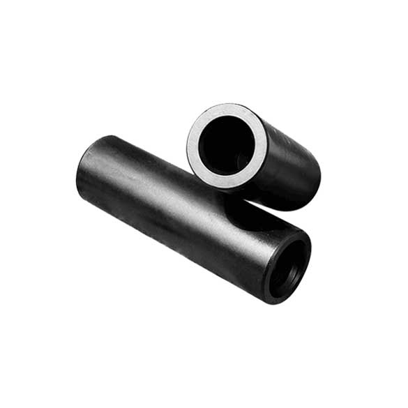
Structure & Design: An MF rod has a male (external) thread on one end and a female (internal) thread on the other. This allows rods to be directly connected to one another without a separate coupling sleeve.
Key Advantages:
Limitations:
Best Applications: MF rods are ideal for long-hole drilling, high-precision projects, and operations where hole deviation must be minimized.
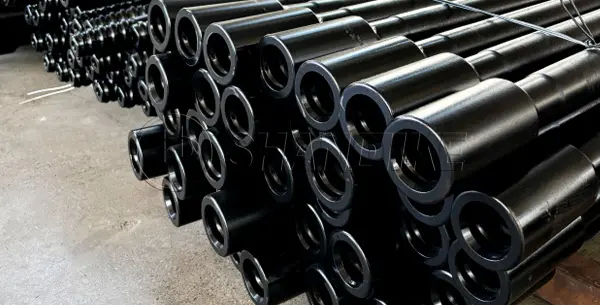
Structure & Design: An extension rod has male threads on both ends. To connect multiple rods and extend the drill string, a separate coupling sleeve is required.
Key Advantages:
Limitations:
Best Applications: Extension rods are a practical and cost-effective solution for step drilling, anchor bolt drilling, and general-purpose drilling where length flexibility is a priority.
The decision between MF rods and extension rods isn’t about which is superior, but which is right for your specific operation. Use this checklist to guide your decision:
The technology behind top hammer drill rods is constantly evolving to meet the demands of modern drilling.
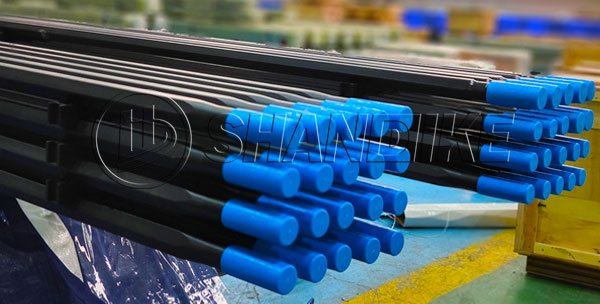
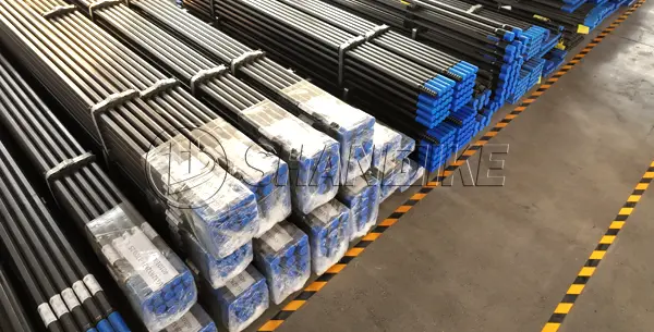
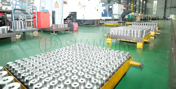
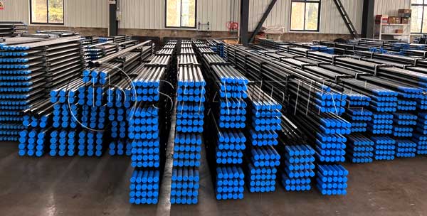
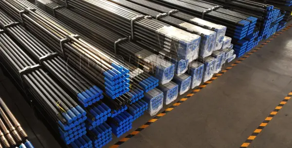
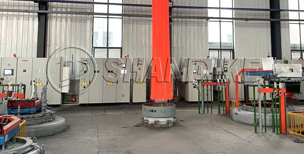
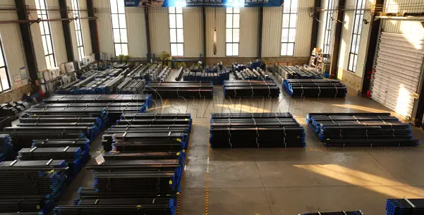
Among the many manufacturers, SHANDIKE stands out as a professional supplier of top hammer drilling tools, specializing in providing high-quality drill rod products for mining, quarrying, and tunneling projects. Its production base in Luoyang is equipped with advanced heat treatment and CNC machining production lines, offering products ranging from R22 to GT60 thread specifications, including both extension rods and MF rods. SHANDIKE holds ISO9001 quality system certification, with products exported to Australia, Canada, the United States, Southeast Asia, and other countries and regions, committed to helping customers reduce operating costs in complex working conditions.
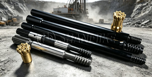
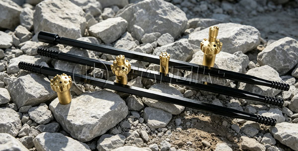
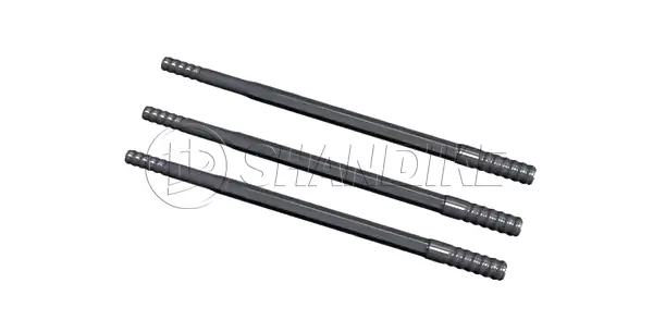
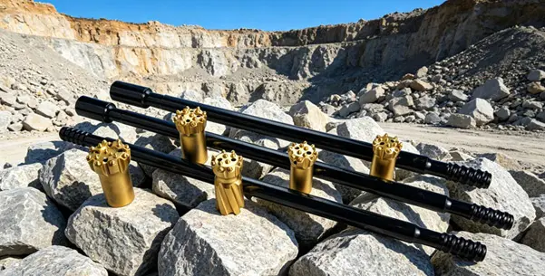
The T51 drifter rod, also commonly referred to as a T51 extension rod or simply a drill rod, is a key component in top hammer drilling operations. Think of it as the “power transmission shaft” between the hydraulic drifter and the drill bit: the high-frequency impact force and rotational torque generated by the drill rig are steadily delivered to the rock face through this rod.
The “T51” in its name refers to the thread connection profile — a 51 mm trapezoidal thread. This design is specifically optimized for deep-hole, high-power bench drilling and production drilling, making it a common heavy-duty configuration.
Because the T51 rod transmits high-frequency impact energy to the bottom of the hole with minimal loss, it is especially well-suited for tough working conditions:
| Parameter | Description |
|---|---|
| Thread Specification | T51 trapezoidal thread (51 mm) |
| Rod Type | Male/Male (M/M) — requires a separate coupling sleeve; Male/Female (M/F) — speed rod with integrated female sleeve on one end |
| Cross Section | Round (lightweight, suitable for conventional extension); Hexagonal (heavy-duty, better rigidity, higher energy transfer and flushing efficiency) |
| Length Range | 610 mm – 6,400 mm |
| Common Length | 3,660 mm (12 ft) |
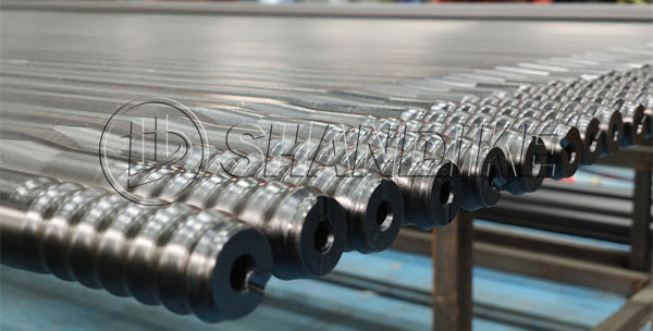
| Material | Fully carburized and heat-treated alloy steel |
| Structural Feature | Hollow rod with a central flushing hole (for compressed air or water to remove cuttings) |
| Compatible Equipment | Top hammer hydraulic drifters, fits major brands |
| Drilling Depth | Deep-hole drilling (actual depth depends on equipment and working conditions) |
| Impact Requirement | High-impact energy, high-frequency impact applications |
Australia is home to some of the world’s most typical hard rock mines, widely distributed across Western Australia (such as the Pilbara iron ore region), Queensland, and New South Wales. These mines are characterized by high hardness and high abrasiveness, primarily producing iron ore, gold, and copper. Drill rods must maintain stable fatigue life under extreme impact and severe wear conditions. As a result, T38 top hammer drill rods are extensively used in Australian mines for open-pit stopes, underground development drifts, and deep hole blasting drilling, where the requirements for thread resistance to unscrewing, steel core toughness, and batch-to-batch consistency are extremely stringent.
The performance of T38 drill rods depends on three main technical indicators:

Australian mining operations demand high product consistency. Unplanned downtime costs far exceed the price of the drill rod itself. Established suppliers ensure stability through:
Luoyang Shandike Mechanical Equipment Co., Ltd. has specialized in rock drilling tools for over a decade. T38 drill rods are manufactured from alloy steel billets with CNC precision machining, and a complete quality control system covers everything from raw materials to finished products. The company’s products have entered the Australian market and gained customer recognition for consistent technical performance.
For detailed technical specifications or pricing, please contact Luoyang Shandike directly.
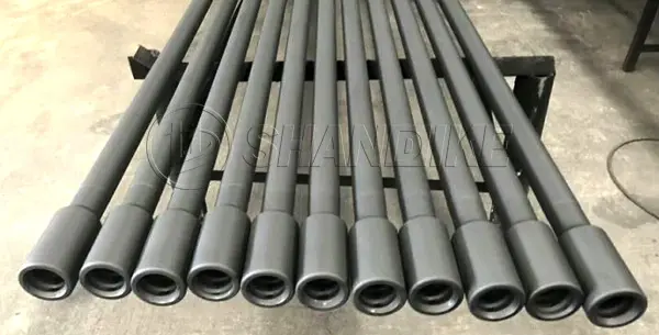
In underground mining and tunneling, whether the hole is straight and the drilling speed is fast largely depends on your drill tools. Among these, tunneling extension rods (also known as drifter rods or extension drill steels) play a critical role in transferring impact energy from the shank adapter to the drill bit.
Thread galling, rod breakage, and costly downtime—these problems often start with the rod. SHANDIKE’s top hammer drilling tools are built for tough rock conditions, with durability as the core advantage.
Designed to fit various drill jumbos and rock conditions, we offer a wide range of sizes:
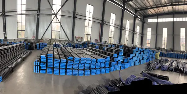
SHANDIKE is an ISO9001-certified manufacturer with a 12,000㎡ production base in Luoyang, China, using European-standard steel processing technology.
1. Premium steel and carburization
We use high-strength hollow alloy steel (e.g., 23CrNi3Mo or equivalent 4140) with a full carburization heat treatment. The surface and threads achieve high hardness, while the core remains tough, offering strong fatigue resistance and reducing early rod failure.
2. Straight holes, minimal energy loss
Precision CNC thread cutting ensures accurate concentricity. Whether using R32 drifter rods or T45 speed rods, the tight thread fit maximizes energy transfer, resulting in straighter holes and faster penetration rates.
3. Compatible with automated drill rigs
Our M/F speed rods are manufactured with strict tolerances, making them fully compatible with automatic rod handling systems on major rig brands such as Sandvik, Epiroc, and Furukawa.
Beyond tunneling extension rods, SHANDIKE also offers:
From Australia and the US to Peru, South Africa, and Southeast Asia, numerous mines and geotechnical projects use SHANDIKE tools to lower their total cost per meter drilled. Our technical team can customize thread configurations, flushing hole diameters, and heat treatment specifications based on your rock hardness and rig parameters.
For factory-direct wholesale pricing or a product catalog, reach out to us. We reply within 24 hours.
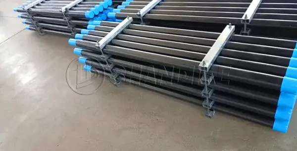
The 3660mm MF Drill Rod (12 feet in length) is a top hammer extension drill rod specifically designed for deep-hole drilling and high-precision rock drilling operations. Featuring a unique male-female (MF) integrated thread design, this rod offers superior structural rigidity, faster coupling/uncoupling efficiency, and extended service life compared to traditional “male-male” rods used with separate couplings.
As a core component of the drill string system, the 3660mm length is an internationally standard dimension that balances the reach required for deep-hole operations with the practicality of on-site handling.
| Parameter | Specification |
|---|---|
| Product Name | MF Drill Rod / Male-Female Connection Rod / Speed Rod |
| Overall Length | 3660 mm (12 feet / 12FT) |
| Diameter Options | Typically 32mm – 46mm rod body (Common: Hex32, Hex35, Rnd39, Rnd46) |
| Thread Types | R32, R38, T38, T45, T51 (Trapezoidal or rope thread) |
| Treatment Process | Fully Carburized or Induction Hardened (thread ends) |
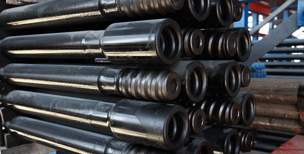
Traditional drill rods require a separate coupling sleeve to connect rod sections. The MF drill rod integrates the female thread directly into one end of the rod body. This design eliminates the microscopic gaps between the sleeve and the rod, creating a tighter connection:
In confined underground environments, loose small components (coupling sleeves) are easily lost and difficult to manage.
The 3660mm MF drill rod must withstand high impact energy and rotational torque, requiring high-quality materials:
| Feature | Traditional Rod + Coupling | MF Male-Female Rod |
|---|---|---|
| Connection Rigidity | Moderate (with clearance) | High (Rigid connection, minimal deviation) |
| Assembly Difficulty | Requires separate coupling handling | Fast, integrated design |
| Application | Shallow holes, low-cost operations | Deep holes, high precision, high efficiency |
The 3660mm MF drill rod is widely used in the following conditions:
When selecting the 3660mm MF drill rod, match the thread to your rock drill model:
Summary:
Choosing the 3660mm MF Drill Rod means selecting higher drilling accuracy, lower consumable costs (no couplings needed), and faster penetration rates. It represents an ideal solution for achieving high-efficiency, low-cost drilling in modern mechanized rock drilling operations.
South Africa’s deep-level underground gold and platinum mines present some of the most punishing environments in the global mining sector. Navigating narrow reefs and ultra-hard rock formations requires drilling equipment capable of handling high-frequency impacts and immense torsional stress. For procurement managers and mining contractors, securing reliable drill rods suppliers in south africa is the first step toward optimizing cost-per-meter and securing uninterrupted project uptime.
While surface operations often rely on heavy air drilling, underground mechanized mining, drifting, and tunneling depend entirely on high-performance top hammer drilling systems.
The Critical Role of Top Hammer Rods in South African Mining
Top hammer drilling utilizes a hydraulic rock drill that transmits high-frequency percussion energy directly through the drill string to the rock face. In South Africa’s deep-reef mines (such as those in the Witwatersrand and Bushveld Complex), top hammer systems are irreplaceable for:
Because the impact energy travels through the steel, choosing premium drill rod manufacturers South Africa ensures that your rods resist fatigue, thread stripping, and mid-hole snapping under immense stress.
Premium Top Hammer Consumables Available in the Region
Leading drill rods suppliers in south africa cater to the underground sector by stocking a precise range of threaded drill steels:
1. Drifting and Tunneling Rods
Designed for underground mechanized jumbos. These rods feature reinforced rod ends to maximize thread life. Standard configurations include R25, R28, R32, and SR35 threads in lengths ranging from 2.4 meters to 4.3 meters, perfectly matching regional underground development rigs.
2. Extension Drill Rods
For long-hole production drilling, underground operators use round or hexagonal extension steels. Trusted local suppliers provide standard R32, T38, T45, T51, and GT60 thread designs. Hexagonal rods offer added rigidity for straighter holes, while round rods optimize flushing in deep holes.
3. MF (Male/Female) Rods
MF drill rods are increasingly favored by automated underground rigs in South Africa. By integrating the coupling sleeve directly into the tool joint, MF rods offer more rigid connections, simpler handling, and a faster rod-changing sequence compared to traditional separate coupling systems.
Technical Specifications: Top Hammer vs. DTH in South Africa
Understanding the mechanical differences helps procurement teams match the right consumables to the job:
| Drill System Feature | Top Hammer (Underground Dominant) | Down-The-Hole / DTH (Surface Dominant) |
|---|---|---|
| Typical Hole Diameter | 38mm – 115mm (Small to Medium) | 115mm – 250mm+ (Large Hole) |
| Energy Transmission | Through the drill steel from the top | Directly at the bottom of the hole |
| Key Consumables | Extension Rods, Shank Adapters, Couplings | DTH Drill Rods, Sub Adapters, Hammers |
| Primary South African Use | Underground Gold, Platinum, Tunneling | Open-cast Coal, Iron Ore, Water Boreholes |
Key Criteria for Selecting a Top Hammer Supplier
To maximize your drill rig’s efficiency, always evaluate potential drill rods suppliers in south africa based on these strict industrial benchmarks:
Booth Number: 409
Date: June 8–11, 2026
Location: Antofagasta Fairgrounds, Antofagasta, Chile
Dear Global Mining Partners,
Luoyang Shandike Mechanical Equipment Co., Ltd. sincerely invites you to Expo Nor Chile 2026, and welcomes you to visit our Booth 409.
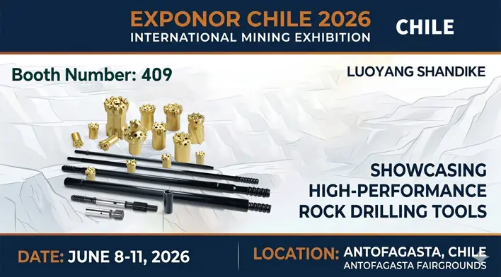
As a professional manufacturer specializing in hollow drill steel and tapered drill rods since 2010, Shandike will showcase the following high-performance rock drilling tools at the exhibition:
Including:
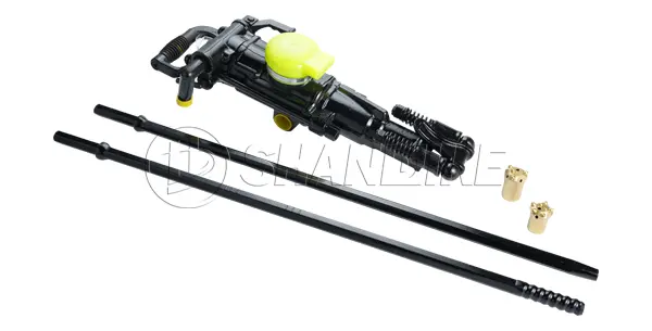
Mainly used with hand-held, air-leg, and rail-type pneumatic rock drills for:
Main products include:
Shandike products have been exported to Australia, Canada, the United States, Peru, Indonesia, Malaysia, the Philippines, South Korea, South Africa and many other countries and regions. With reliable product quality and long service life, Shandike has won high praise from customers and established long-term cooperative relationships worldwide.
We currently hold more than 30% market share in China, with a nationwide sales network and multiple overseas sales outlets.
📅 Expo Date: June 8–11, 2026
📍 Location: Antofagasta Fairgrounds, Antofagasta, Chile
🏷 Shandike Booth Number: 409
We look forward to welcoming you at our booth to explore high-efficiency and durable rock drilling solutions together.
Luoyang Shandike Mechanical Equipment Co., Ltd.
Professional · Reliable · Serving the Globe
In top hammer rock drilling, choosing the right drill string components directly impacts your daily productivity and drilling costs. The R25 drill rod is a globally recognized industry standard for small-hole drilling, tunneling, and mining applications.

An R25 drill rod (also called an R25 extension rod) is a hollow steel bar used to connect the rock drill machine to the drill bit.
To ensure the rods fit your existing drilling rigs (such as Sandvik, Epiroc, or Furukawa), look for these standard specifications:
R25 drill tools are designed for small hole diameters, typically ranging from 33mm to 45mm. They are widely used in:
High-quality manufacturers use advanced processes to ensure the rods can handle high impact without breaking:
Investing in reliable, heat-treated R25 drill rods reduces machine downtime and lowers your overall cost per meter.
Do you need a price quote for bulk orders, or are you looking for a specific length for your drilling equipment? Let us know your requirements today!
In the demanding world of top hammer drilling, maximizing efficiency and minimizing downtime are the keys to profitability. Whether you are managing an open-pit mining operation, driving a tunnel, or executing a heavy civil engineering project, your choice of rock drilling tools directly impacts your bottom line.
Among the industry-standard consumables, the T45 extension rod stands out as a critical component for medium-to-deep hole drilling. But what exactly is a T45 extension rod, and how do you choose the right one for your fleet? This comprehensive guide breaks down everything you need to know.
A T45 extension rod (also known as a T45 drill rod or speed rod) is a heavy-duty steel component used in top hammer drilling systems. Its primary function is to transmit the impact energy, rotation torque, and feed pressure from the rock drill drifter down to the drill bit.
As the drill hole goes deeper, multiple extension rods are connected end-to-end to achieve the target depth. The “T45” designation signifies a specific industry-standard thread profile:
“T” (Trapezoidal): Refers to the trapezoidal thread design, which offers excellent wear resistance, high torque transmission, and easy uncoupling.
“45”: Indicates a nominal thread diameter of approximately 45mm (1.75 inches).
To optimize your drilling performance, it is vital to understand the structural properties of T45 rods. Premium manufacturers produce these rods using advanced metallurgical processes to handle extreme stress.
1. R46 Round and Hexagonal Bodies
T45 threads are most commonly machined onto Round 46 (R46) steel bars. Round rods provide higher rigidity, better flushing clearance, and straightness in deep holes. Hexagonal variants are occasionally used for applications requiring easier manual uncoupling.
2. Flushing Holes
Every T45 rod features a central flushing hole (typically 17mm or 21.5mm in diameter). This channel allows water or compressed air to flow directly to the bit, cooling the cutting edges and flushing rock cuttings out of the hole.
3. Length Options
Standard lengths vary depending on the drill rig’s feed size. Common lengths include:
T45 extension rods are engineered in two distinct structural configurations to suit different rig configurations and operator preferences:
Male/Female (MF) Rods / Speed Rods
MF rods feature a male thread on one end and an integrated female sleeve on the other.
Male/Male (MM) Rods
MM rods feature male threads on both ends and require a separate T45 coupling sleeve to connect to the next rod.
T45 drilling tools are optimized for drilling hole diameters ranging from 89mm to 127mm (3.5″ to 5″). They are the industry workhorses in several sectors:
Because drilling tools operate under intense friction and impact, they are subject to fatigue. To lower your total drilling cost per meter, follow these maintenance best practices:
Finding the right top hammer drilling rod price is critical for keeping your underground mining, tunneling, or quarrying project on budget. However, a low upfront cost can lead to expensive premature failures down the hole—especially under the high-impact stress of top hammer drilling.
This guide breaks down current market rates for top hammer rods, the hidden factors that drive their costs, and how to get the best value for your investment.
Top hammer drill rod prices vary based on diameter, thread type, and length. Below are general benchmarks for standard industrial top hammer rods in 2026:
Note: Bulk orders of top hammer rods typically qualify for 10% to 20% volume discounts from direct manufacturers.
When comparing quotes, the price of a top hammer rod is determined by five primary variables:
| Feature | Low-Cost Top Hammer Rods | Premium Top Hammer Rods |
|---|---|---|
| Upfront Price | Low ($) | High ($$$) |
| Steel Source | Non-verified scrap/re-rolled | Certified virgin alloy (e.g., 42CrMo) |
| Thread Type | Cut threads, loose tolerances | Rolled threads, precision ground |
| Heat Treatment | Minimal or uneven | Full-length induction hardened |
| Risk Factor | High risk of thread stripping or breakage | Minimal risk; predictable wear |
| Best Used For | Shallow holes, soft limestone, light demolition | Deep blast holes, hard granite, high-production quarries |
Saving money on top hammer rods isn’t about finding the lowest retail price. True cost efficiency comes from minimizing cost-per-meter drilled.
Because steel prices and alloy surcharges fluctuate weekly, online price lists are often outdated. The best way to secure an accurate budget is to request a direct factory quote for your specific top hammer rod thread type (R32, T38, T45, T51) and length.
The SHANDIKE GT60 Drifter Rod is a high-strength, heavy-duty rock drilling tool engineered for modern high-power top hammer drill rigs. It is primarily utilized in demanding environments such as open-pit mining, tunneling, and long-hole bench blasting in quarries.
1. Thread & Joint Configurations
2. Common Technical Parameters
If you are looking for cost-effective rock drilling solutions, please feel free to contact our technical experts for professional selection advice. Click below or send an inquiry today to get the latest competitive quote for SHANDIKE GT60 Drifter Rods!
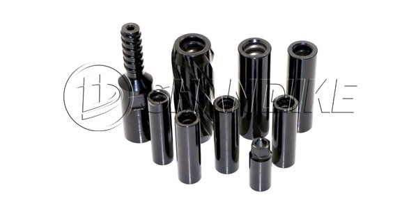
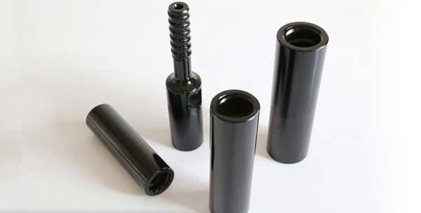
In top hammer rock drilling, energy transfer efficiency determines your drilling speed and cost per meter. T45 coupling sleeves are critical components that bridge the drill string, ensuring seamless impact energy transmission from the drifter to the rock bit.
Choosing high-quality T45 coupling sleeves minimizes thread wear, prevents energy loss, and extends the lifespan of your extension rods.
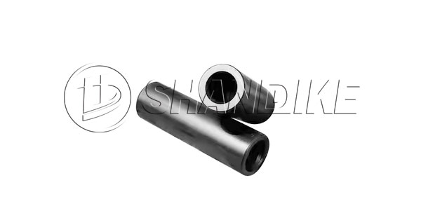
A T45 coupling sleeve, also known as a T45 adapter, is a heavy-duty steel tube featuring internal T45 threads on both ends. It is engineered specifically to connect T45 extension rods to shank adapters or other drill rods in bench drilling, production drilling, and long-hole tunneling.
With a nominal thread diameter of 45mm, the T45 system is the industry standard for medium-sized hole rock drilling operations worldwide.
High-quality T45 sleeves provide a tight, flush joint connection. This ensures that the shock waves from the rock drill piston travel straight into the drill bit without scattering, maintaining high penetration rates.
Precision-machined T45 trapezoidal threads reduce friction during rotation. This eliminates uncoupling issues and protects expensive extension drill steel from premature stripping or damage.
T45 couplings maintain perfect linearity throughout the drill string. This prevents hole deviation, improves drilling accuracy, and reduces bending stress on your drilling rigs.
| Specification Parameter | Technical Data / Standard Value |
|---|---|
| Thread Type | T45 (Trapezoidal Thread) |
| Common Lengths | 210mm / 250mm |
| Outer Diameter (OD) | Approx. 63mm |
| Core Material | High-Grade Structural Alloy Steel |
| Manufacturing Process | CNC Machining & Advanced Heat Treatment |
| Primary Application | Bench Drilling, Production Drilling, Tunneling |
Depending on your specific geological conditions and rig setup, you can select from two main structural designs:
This is the most widely used configuration. It features a solid middle section (bridge) inside the sleeve. The T45 drill rods thread into both ends and meet firmly at the center bridge, preventing the sleeve from walking down the drill string during operation.
Full-bridge sleeves eliminate the risk of the coupling sliding along the joints. They offer superior rigidity across the entire joint area and are highly recommended for drilling in heavily fractured, broken, or unstable rock formations.
Not all T45 coupling sleeves are manufactured to the same standard. Industrial-grade drilling demands state-of-the-art metallurgical processing:
How to Extend the Lifespan of Your T45 Coupling Sleeves
To maximize your return on investment (ROI) and minimize drill string downtime, follow these maintenance best practices:
Conclusion: Partner with a Trusted T45 Rock Drilling Tools Manufacturer
Investing in premium T45 coupling sleeves directly reduces your cost-per-foot and keeps your drilling operations running at peak efficiency. Whether you are operating in mining, quarrying, or civil engineering, using the right drilling accessories is the key to productivity.
Contact our engineering team today to get a competitive quote on standard or customized T45 coupling sleeves optimized for your specific drilling environment.
T51 Drill Rod Fracture Analysis and Prevention Recommendations
Fracture of the T51 drill rod is typically not caused by a single factor, but rather by the combined effect of stress concentration and material fatigue under extreme operating conditions.
The following is an analysis of the main causes of T51 drill rod fracture and corresponding prevention recommendations:
Choosing the best R32, T38, T45, and T51 drill rods is critical for efficient rock drilling, whether you are working in underground mining, tunneling, or surface construction. High-quality drill rods reduce downtime, increase penetration rates, and lower overall drilling costs.
At SHANDIKE, we specialize in manufacturing top-tier threaded drill rods that meet international standards. Our rods are engineered for extreme durability and performance in hard rock conditions.
In this article, we’ll explore the key features of SHANDIKE’s R32, T38, T45, and T51 drill rods and explain why they are the preferred choice for professional drillers worldwide.
These designations refer to the thread connection type and rod diameter used in rock drilling systems:
| Thread Type | Shank Diameter | Typical Application |
|---|---|---|
| R32 | 32 mm | Small to medium hole sizes, light to medium rock conditions |
| T38 | 38 mm | Medium hole depths, common in mining and tunneling |
| T45 | 45 mm | Deeper holes, demanding rock formations |
| T51 | 51 mm | Large diameter holes, deep drilling, heavy-duty conditions |
SHANDIKE produces all four types with case-hardened steel bodies, precision-machined threads, and optimized heat treatment for maximum fatigue resistance.
SHANDIKE uses high-grade alloy steel (often 22CrMoH or equivalent) with strict heat treatment processes. This ensures:
Our threads are manufactured with tight tolerances to ensure:
We apply deep case hardening to the rod ends while maintaining a tough core. This balances wear resistance and impact toughness – a key feature of the best R32, T38, T45, and T51 drill rods.
Every batch of SHANDIKE rods undergoes:
| Feature | SHANDIKE Rods | Standard Economy Rods |
|---|---|---|
| Steel grade | Alloy steel (22CrMoH) | Medium carbon steel |
| Heat treatment | Precision multi-stage | Basic induction |
| Thread accuracy | ISO 10207 compliant | Variable |
| Service life (m drilled) | 25-40% longer | – |
| Failure rate | <0.5% during warranty | Higher |
SHANDIKE’s R32, T38, T45, and T51 drill rods are widely used in:
In the development of Australia’s vast mineral resources, the choice of drilling equipment directly impacts project efficiency and cost control. R32 drill pipe, with its superior performance and durability, is becoming an increasingly important focus for mining companies. However, in the face of constantly fluctuating market conditions, obtaining accurate R32 drill pipe price information has become a common challenge for many enterprises.
R32 drill pipe is made of high-quality alloy steel and undergoes a special heat treatment process, giving it excellent torque resistance and wear resistance, making it particularly suitable for Australia’s diverse geological conditions. From iron ore mines in Western Australia to coal mines in Queensland, R32 drill pipe demonstrates stable drilling performance and a longer service life in various complex formations.
The advantages of this drill pipe are not only reflected in its superior physical properties, but also in the overall economic benefits it can bring to the project—reducing replacement frequency, reducing downtime, and improving drilling efficiency. These factors work together to ultimately optimize the total project cost.

The price of R32 drill pipe in the Australian market is not fixed but is influenced by a variety of factors:
Raw material cost fluctuations: Changes in global steel market prices directly affect drill pipe production costs.
Transportation and logistics costs: International shipping prices, domestic shipping distances and methods within Australia.
Specifications and customization requirements: Drill pipes of different lengths, wall thicknesses, and special treatments have significant price differences.
Purchasing scale: Bulk orders usually result in more competitive unit prices.
Market supply and demand: Mining cycle fluctuations affect equipment demand and prices.
Accurate Quote: Why Professional Consultation is Essential?
Obtaining an accurate R32 drill pipe quote involves much more than just a number; it requires comprehensive consideration:
Project Matching Analysis: Your specific geological conditions, drilling depth, and strength requirements.
Full Lifecycle Cost Assessment: Including initial procurement, operation, maintenance, and replacement costs.
Supply Chain Stability: Delivery time, inventory status, and the possibility of long-term cooperation.
Additional Service Value: Technical support, after-sales service, and warranty terms.
Contact Luoyang Shandi Ke: Get Your Customized Quote
You’re comparing prices for 38mm hex extension drill rods. That’s natural. Cost is always a key factor when procuring rock drilling tools.But as a professional, you know better than anyone: The lowest “sticker” price often comes with the highest total cost of ownership.The true value of a 38mm Hex Extension Rod is never reflected on the purchase invoice—it’s embedded in every single drilling cycle.
What does a hex connection with micron-level precision mean? It means zero-clearance power transmission. It means every impact is fully delivered to the rock, not wasted in inefficient collisions between the rod and the drill. It translates to faster penetration rates, reduced machine vibration, and extended equipment life. Our 38mm rods are forged from a specific micro-alloy steel formula, engineered to balance extreme hardness with fatigue resistance. This prevents premature brittle fractures or excessive wear, extending your work cycles in meters drilled, not hours lost to downtime.
Consider this: during a critical project phase, what is the real cost of replacing a failed rod due to wear or breakage? It’s not just the cost of a new rod. It’s the cost of machine downtime, labor, and delays cascading across the entire worksite. Our goal is not to be the cheapest line item on your quote, but to be the most reliable and stable multiplier in your productivity equation. Through optimized heat treatment and surface hardening technologies, our rods maintain their integrity in the toughest formations, minimizing change-out frequency—that’s the most fundamental protection for your bottom line.
Every rock drill has its unique “pulse.” Our 38mm hex extension rods are not just made to dimensional standards; they are designed as a precision-engineered extension of your rig’s power train. We focus on torque transmission efficiency, stress distribution, and wave impedance matching. This ensures the rod works in synergy with your equipment—whether it’s Sandvik, Atlas Copco, or other leading brands—to deliver 100% of its intended performance while protecting the valuable drill head from damaging recoil.
So, when you evaluate the “38mm Hex Extension Rod Price,” you are really assessing a critical investment for your project’s success.
We invite you to make a more meaningful comparison: look beyond the price per rod, and calculate the cost per drilled meter.
Request our detailed Technical Specification & TCO Analysis Portfolio to see how our 38mm hex extension rods optimize your total cost of ownership in real-world conditions. Let us respond to your price inquiry with a professional engineering solution.
— Engineered for Value, Not Just Supplied as a Product —